Continue to Site

Welcome to our site!

Electro Tech is an online community (with over 170,000 members) who enjoy talking about and building electronic circuits, projects and gadgets. To participate you need to register. Registration is free. Click here to register now.

  • Welcome to our site! Electro Tech is an online community (with over 170,000 members) who enjoy talking about and building electronic circuits, projects and gadgets. To participate you need to register. Registration is free. Click here to register now.

Measuring current with a common ground panel meter?

Status
Not open for further replies.

Revolvr

Member
Hi all, happy new year

I have a power supply I want to add a current meter to. The power supply has a 5VDC output I'll use for the meter, and a variable DC output. The meter is a common LED panel meter that measures voltage drop across inputs; it has a common ground with it's supply and the voltage being measured.

How can I hook this up to measure current drawn from the variable power supply? I understand how to create a shunt and set it up to measure a certain voltage range. Just not how to hook it up with a common ground...

TIA

-- Dan
 
Hi Happy New Year !

What is the measuring range of the LED panel meter ? If it is of volts, say 5 volts, and if you are to measure up to 2 Amperes, the current shunt will become a heater of 5X2= 10 Watts -- no good!

So I would recommend one working for around 0.1V only.

In fitting into the regulator circuit, make sure the voltage drop of the shunt would not interefere with the regulator feedback circuit.

To facilitate discussion, can you sketch out the regulator circuit please ?
 
Look into using a high side current shunt monitor IC like the INA138 or equiv. You can also use an Op-Amp as a differential amplifier to reference your shunt voltage drop to ground but it is a little harder to get accurate results this way.
 
Last edited:
Current circuit attached. The panel meter needs up to 200mV across the shunt. Current will be 1A or less. The meter itself draws 60mA at 5V.

-- Dan
 

Attachments

  • panelmeter.jpg
    panelmeter.jpg
    55.6 KB · Views: 419
Referring to the circuit, I assume that the Meter Power(-) is connected directly to the common ground of LM317T.

The question now is whether the input to the panel meter, +IN and -IN would be able to accept and measure the low level voltage (0 to +200 mV) at the common ground ? In other words, whether the -IN can be connected to Meter Power(-) directly without affecting the performance of the Meter ?

Only if the answer is YES then you can succeed. Please ensure this first.
 
The circuit below will work as long as the 12V input (-) is not common with Vout (-).... Use a 0.1:eek:
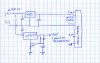
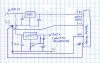
hm: shunt for 100mV @ 1amp. Note the single point ground.
 

Attachments

  • panelmeter.jpg
    panelmeter.jpg
    60.6 KB · Views: 313
I totally agree with kchristle.

Note however that the -IN is now connected directly to Meter Power(-), please ensure this is OK for the Panel Meter.
 
By the way kchristle, do you use a special program to modify the .jpg circuit diagram ? I just wonder if there is one good for this. It is handy for small amendments to circuits, as compoared to redrawing the whole circuit on Eagle, say.
 
Thanks everybody - I understand how this works now. Also simulated it in SPICE and it works OK there. Using an op-amp is an interesting idea though I may pursue.

Olihou, I use Paint Shop Pro for that kind of image modification, erasing, moving parts, drawing lines, adding text etc., is easy.

-- Dan
 
Status
Not open for further replies.

Latest threads

New Articles From Microcontroller Tips

Back
Top