Continue to Site

Welcome to our site!

Electro Tech is an online community (with over 170,000 members) who enjoy talking about and building electronic circuits, projects and gadgets. To participate you need to register. Registration is free. Click here to register now.

  • Welcome to our site! Electro Tech is an online community (with over 170,000 members) who enjoy talking about and building electronic circuits, projects and gadgets. To participate you need to register. Registration is free. Click here to register now.

maybe this is my problem

Status
Not open for further replies.

mstechca

New Member
Have a look:

So far, I am able to produce myself a superregen that operates in the FM band, BUT, I want to try to pull in some TV stations. To start, channel 11 (local).

Here is the interesting part, I am able to pick up the channel that spits out random data. I think this is some RTTY or data communications channel. The rest of the stuff I am picking up is just whitenoise.

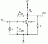
Take a look at the following schematic. This is the circuit I use directly after the superregen detector. My main concern here is capacitor X and capacitor Y. Do any of these capacitors introduce a filter? and what kind?

Why do I ask? because different capacitors provide different volume, and different sound output. It seems that the larger the capacitor (up to about 33nF) the louder the volume. The lower value capacitors seem to reduce whitenoise greatly, but the volume is reduced.

If any of you can show me an oscillator or a filter in this circuit, I would like to know because this is probably screwing up my signal.
 

Attachments

  • amp_904.gif
    amp_904.gif
    1.5 KB · Views: 425
You show an audio amplifier stage with a missing supply bypass capacitor.

It has two lowpass filters:
1) Capacitor x cuts-off input high frequencies depending on the source impedance.
2) Capacitor y cuts-off output high frequencies depending on the 27k collector resistor and the load impedance.

If you feed a high level, low impedance RF signal into it, the transistor will rectify it and become an amplifying AM detector.
 
Now I have another question (ok zack, time to take your "I talk too much signature" away. In fact, that signature is MINE! j/k).

It seems that these low pass filters become interesting.

Since I am able to pick up what sounds like packet radio communications, what should I set the filters to, the bandwidth (of the signal), the bandwidth * 2, the bandwidth / 2, 20Khz to cover the audio range (even though I want data), or something else (*gulp*)?

LOL
 
What do you need lowpass filters for? To reduce the "white noise"?
If you can hear the noise and the filter reduces it, then the filter also reduces the high frequency audio in the program.

With the 27k collector resistor and a high impedance load, if capacitor y on the output is 33nF, then its filter action reduces frequencies at and above 180Hz. Just about all treble in the program will be gone.
If you use another filter on the input, the treble reduction will be worse.
Try to feed data through that filter and it won't be data anymore.
 
What do you need lowpass filters for? To reduce the "white noise"?
Basically yes, and to prevent other stations of higher frequency from screwing around with my receiver.

With the 27k collector resistor and a high impedance load, if capacitor y on the output is 33nF, then its filter action reduces frequencies at and above 180Hz.
180Hz?

How did you get 180Hz?

to me, I would use 1/(2 * load resistor * 33nF), and I wouldn't get that low of an aswer.

But if I use 1/(2 * 1.5M * 33nF), I get about 20Hz.

Do I have to use 2 * pi in the equation even though I'm dealing with resistors and capacitors and not inductors?
 
The poor selectivity (interference from other stations) of your super-regen is because it has only a single RF tuned circuit. "Real" radios have many RF tuned circuits for excellent selectivity.

The super-regen has already detected the audio modulation so audio filtering won't reduce RF interference.

1 divided by 2 times pi times 27k times 33nF equals 180Hz. If you don't use pi then maybe you are calculating the weight of the components instead of their cutoff frequency!
With a very high impedance load, a 1.5M resistor feeding a 33nF cap to ground has a lowpass cutoff frequency of 3.2Hz.
 
now that's interesting. I never thought there was a way to calculate weight. I thought it was always measured with a scale.
 
A scale is a protective part of fish skin, isn't it? :lol: :lol:
 
Status
Not open for further replies.

Latest threads

New Articles From Microcontroller Tips

Back
Top