Continue to Site

Welcome to our site!

Electro Tech is an online community (with over 170,000 members) who enjoy talking about and building electronic circuits, projects and gadgets. To participate you need to register. Registration is free. Click here to register now.

  • Welcome to our site! Electro Tech is an online community (with over 170,000 members) who enjoy talking about and building electronic circuits, projects and gadgets. To participate you need to register. Registration is free. Click here to register now.

maxitronix 300 in 1 project 20

Status
Not open for further replies.

chopchip

New Member
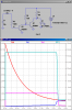
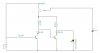
i thought i would ask if anyone is familiar with this electronic timer circuit. i cant figure it out. the capacitor discharges and the small current from emiter to base makes the transistor conduct. for the rest i cant fathom it. can someone shed some light on this? why doesnt current just flow thru the diode when the switch is down constantly, i wired it up and the diode emits light for as long as the capacitor is discharging. but why? why doesnt the led just continue to emit light since it is in circuit with the battery and there is no transistor in its path. and how does the conducting first transistor influence the second one and how does this limit the amount of time the LED emits light?


the transistors are not the ones used in the original circuit they are just random ones i picked.

thanks
stumped
 

Attachments

  • NONAME..JPG
    NONAME..JPG
    23.1 KB · Views: 253
Last edited:
When the capacitor has no voltage, T1 is off. R1 sends current to the base of T2. T2 conducts, dumping the current through R3 to ground and the diode has none.

When C1 has some voltage, some current flows through R1, turning on T1, but getting weaker as time goes by. If T1 ever becomes fully on, it dumps the current through R2 so T2 has no base current. T2 is off and the current through R3 flows through the diode.

As the current through R1 gets smaller and smaller, T1 turns off and R2 turns on T2 which dumps the current through R3 and the diode has none.
 
resistors

i didnt know resistors sent current. when Q1 is off R1 sends current to Q2? how does Q2 dump the current through R3 to ground? where is ground? why would current flow through Q2 and not the diode when Q2 is conducting. the emitter-collector and diode leads go to the same resistor, i assume current finds the path of least resistance.

i will meditate on your reply and seek guidance in the mind's eye

thanks
 
Last edited:
Whenever a voltage is applied to a resistor, some current flows. The current is sent through the resistor. Ground is the bottom line of the drawing. Transistors are devices that allow current to flow from their collectors to their emitters when current flows from their bases to their emitters. That is how Q2 becoms the path of least resistance.
 
when the switch is in the "up" position current flows through the capacitor until the voltage across it equals the supply voltage - the capacitor is fully charged.

current only flows from battery to capacitor back to the battery.

when the switch is in the down position the capacitor discharges via Q1. the emitter-collector current meets the mighty 10k R1 consequently current will flow through the LED because of the low resistance value of R3.

when the capacitor has fully discharged and Q1 is no longer conducting current flows through the emitter on Q2 to its base. despite the small value of this emitter-base current, in view of mighty R2, it conducts heavily and the LED is not lit.

for some reason the current prefers to flow through Q2 rather than the LED even though the LED-R2 branch appears to have a lower resistance. why is this?

is my reasoning partialy correct here?

thanks
 
There is no "LED R2 branch". R2 does not bring current to the LED. It brings current to Q1.
 
This might help explain how it works. It is a very bad circuit, because it draws power even after the led turns off.
 

Attachments

  • RC.png
    RC.png
    31.9 KB · Views: 208
Status
Not open for further replies.

New Articles From Microcontroller Tips

Back
Top