Continue to Site

Welcome to our site!

Electro Tech is an online community (with over 170,000 members) who enjoy talking about and building electronic circuits, projects and gadgets. To participate you need to register. Registration is free. Click here to register now.

  • Welcome to our site! Electro Tech is an online community (with over 170,000 members) who enjoy talking about and building electronic circuits, projects and gadgets. To participate you need to register. Registration is free. Click here to register now.

Maximum gain of comparator?

instrumental

New Member
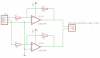
Hello. I am using salvaged HDD motor as a sine wave source and I'm feeding those signals into LM324N using schematic in attachment. Basically, idea is to spin the motor, motor generates sine signals, comparator converts them into square and then I'm feeding the signals into microcontroller, to read input data. Original schematic suggested 1k resistor for R1 and R3, and 10k for R2 and R4, but that didn't gave me good enough resolution from the disk - I had to spin it faster to detect signal change. So I'm using 100/22k combination, which works exactly like I want it. Now, obviously, I can't get infinite signal gain, so what I'm asking is, what resistor combination would result in maximum gain in this specific scenario? I even tried to switch 100ohm resistors with 47ohm, just to see what happens, but nothing changed. I'm really lost on op-amps and comparators, so if anyone has good literature/video/links to suggest, I would be grateful.
 

Attachments

  • hddj.png
    hddj.png
    8.2 KB · Views: 289
The old LM324 has poor high frequency response. With a 5V supply its gain at 10kHz is only about 20 times.
Your resistors provide DC positive feedback which might be causing the output to latch high and low and needing a whopping big signal level to overcome it
An amplifier uses negative feedback.
 
what resistor combination would result in maximum gain in this specific scenario?
Remove all resistors for maximum gain. But maximum gain might introduce instability.
I agree with AG about the feedback. Also, you may need to provide clamping diodes to prevent the inputs being driven too far below the amps' negative supply.
 
Last edited:
Why not use a comparator like the LM339?
 

Attachments

  • 3 phase.png
    3 phase.png
    110.3 KB · Views: 284
Remove all resistors for maximum gain. But maximum gain might introduce instability.

I am taking care of instabilities in software, not a big issue. I tried to remove all resistors, but then I didn't get no input data at all. So I removed only R1/R3 and left resistors R2/R4, it worked again. Any explanation why?

In the meantime I learned that those resistors create a hysteresis, areas where output is considered to be high, low, and empty areas where output doesn't change state. Therefore, there is no actual gain, only a threshold. So, according to this formula:

Vth+ = - VN ∙ R1 / R2
Vth- = - VP ∙ R1 / R2

It shouldn't matter that I removed all resistors, but it does. I'm confused. Oh, and, I don't see the reason to use those diodes here, maximum/minimum voltage I can create is 500mV, give or take few mV.
 
Last edited:
Looks like a single 5V supply, no bias at all for the opamp, no DC blocking capacitor on the input, and a very poor choice of opamp as well - I'm not surprised it doesn't work.
 
Looks like a single 5V supply, no bias at all for the opamp, no DC blocking capacitor on the input, and a very poor choice of opamp as well - I'm not surprised it doesn't work.
 
Yep, your right. If you never spin it fast enough to go more than a few tenths below ground no diode or resistor needed. Your also right it should work without any resistors. Might want to scope both inputs.
 
Looks like a single 5V supply, no bias at all for the opamp, no DC blocking capacitor on the input, and a very poor choice of opamp as well - I'm not surprised it doesn't work.

Sorry - I'm not an expert in this area, if I were I wouldn't be asking for help here, would I?

Also, your comment isn't helpful at all. Bias? DC blocking capacitor? I'm not sure what that even means. Poor choice of opamp? Suggest me something else then instead of just critising.

ronv: I will try it with LM339 using same schematics and report back.
 
Sorry - I'm not an expert in this area, if I were I wouldn't be asking for help here, would I?

Also, your comment isn't helpful at all. Bias? DC blocking capacitor? I'm not sure what that even means. Poor choice of opamp? Suggest me something else then instead of just criticizing.
I corrected your poor spelling.
We are electronic geeks, not teachers of the basics of electronics that is taught in high school. Do you want somebody to design the simple circuit for you for free?
What is the "data" you will get from spinning a motor? Its RPM? Then the motor is simply a tachometer? For a kid's bicycle?
 
Do you want somebody to design the simple circuit for you for free?

No. I simply wanted explanation about why LM324N solution doesn't work with no resistors.

What is the "data" you will get from spinning a motor? Its RPM? Then the motor is simply a tachometer? For a kid's bicycle?

Purpose of spinning a motor is to convert inputs to digital signal, and after that I'm using it as a rotary encoder. As I said, I'll try it with LM339 and see what happens.
 
Another question - I was reading datasheet for LM339 and I was left confused with these two parameters (in attachment). What is the difference between input voltage and common-mode voltage range? Basically, I'm not sure what is the minimum voltage I can apply to LM339 inputs (considering that I can generate -500mV).
 

Attachments

  • ScreenShot128.png
    ScreenShot128.png
    47 KB · Views: 237
  • ScreenShot130.png
    ScreenShot130.png
    76.2 KB · Views: 229
The maximum allowed negative input voltage is only -0.3V because more negative voltage might damage the inputs. The circuit shown in post #5 shows input resistors and BAT54 Schottky diode clamps at the comparator inputs to prevent inputs from going more negative than -0.3V.
The input common-mode voltage range goes from 0V to 1.5v less than the positive supply voltage. Input voltages higher than this range cause the inputs to stop working correctly because the inputs are the bases of PNP darlington transistors.

The LM324 quad has 4 opamps inside, the LM358 dual has 2 of the same opamps inside. The LM339 quad and the LM393 dual comparators have exactly the same input ratings as those opamps.
 
The maximum allowed negative input voltage is only -0.3V because more negative voltage might damage the inputs. The input common-mode voltage range goes from 0V to 1.5v less than the positive supply voltage. Input voltages higher than this range cause the inputs to stop working correctly because the inputs are the bases of PNP darlington transistors.

This makes no sense to me. How can it have voltage range less than maximum allowed negative input voltage?
 
Last edited:
More than -0.3V on an input might damage the input. The inputs are guaranteed to work properly from 0V to 1.5V less than the positive supply voltage.
 
More than -0.3V on an input might damage the input. The inputs are guaranteed to work properly from 0V to 1.5V less than the positive supply voltage.

Ohhh. Now I understand. Feeling dumb now. Thanks a lot, I'm finally getting the hang of this :)

Edit: Two more questions: those 10k/1MOhm resistors set the hysteresis above 50mV for 5V output, and less than 0 for 0V output, am I correct?
Question #2: Can I use BAT46 diode instead of BAT54? They seem to have similiar characteristics, and BAT54 isn't available in my shop.
 
Last edited:
Yes, and yes. You may want like 4.7 meg since your signal is low. Just something to keep it from chattering around the switch point.
 

Latest threads

New Articles From Microcontroller Tips

Back
Top