Hi guys, I had tried using an XR2206 design to try and make a function generator but no matter what I did I just could not get it giving a stable output. So I thought I'd give the Max038 a try and seeing several other people have successfully used them in the past for this purpose.
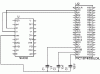
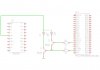
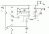
Just wanted to get some input regarding my design at the minute to spot any mistakes and potential problems, its still work-in-progress so I have done a schematic of what I currently have breadboarded at the moment (attached).
I've checked the +/- 12V and +/-5V rails for stability using a scope and there is no noticable ripple. This time I'm taking no chances and used 4700uF 50V electrolytics between the bridge rectifier and the regulators along with 0.1uF.
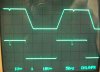
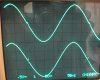
You can see the results of the new circuit using the Max038 Vs the output I was getting from the XR2206 in the photo, there is a slight glitch in the sine wave however it seems I might just have a dodgy potentiometer as just tweaking it eradicates it, can anyone spot any problems with the circuit or anything I should add to improve stability etc? Already betting much better results than I was with the old XR2206 circuit.
Another thing I would like to pick your brains about is a recommendation for an OpAmp for the output stage, I need something dual-rail (+/-12V), the original circuit I borrowed ideas from was a bit obsolete and I've tried searching for an equivalent but with no luck.
I'm planning on adding controls for DC offset, using a PIC 16F4550 (bit overkill) with a 20x4 LCD and a simple pushbutton interface for frequency range selection, SPi digipot for Coarse adjustment with a normal pot for fine adjustment, and frequency counter. Considering my electrical/mechanical rather than electronics background this is a fairly ambitious project for me so all advice and assistance is greatly welcomed")
Just wanted to get some input regarding my design at the minute to spot any mistakes and potential problems, its still work-in-progress so I have done a schematic of what I currently have breadboarded at the moment (attached).
I've checked the +/- 12V and +/-5V rails for stability using a scope and there is no noticable ripple. This time I'm taking no chances and used 4700uF 50V electrolytics between the bridge rectifier and the regulators along with 0.1uF.
You can see the results of the new circuit using the Max038 Vs the output I was getting from the XR2206 in the photo, there is a slight glitch in the sine wave however it seems I might just have a dodgy potentiometer as just tweaking it eradicates it, can anyone spot any problems with the circuit or anything I should add to improve stability etc? Already betting much better results than I was with the old XR2206 circuit.
Another thing I would like to pick your brains about is a recommendation for an OpAmp for the output stage, I need something dual-rail (+/-12V), the original circuit I borrowed ideas from was a bit obsolete and I've tried searching for an equivalent but with no luck.
I'm planning on adding controls for DC offset, using a PIC 16F4550 (bit overkill) with a 20x4 LCD and a simple pushbutton interface for frequency range selection, SPi digipot for Coarse adjustment with a normal pot for fine adjustment, and frequency counter. Considering my electrical/mechanical rather than electronics background this is a fairly ambitious project for me so all advice and assistance is greatly welcomed
Attachments
Last edited: