Continue to Site

Welcome to our site!

Electro Tech is an online community (with over 170,000 members) who enjoy talking about and building electronic circuits, projects and gadgets. To participate you need to register. Registration is free. Click here to register now.

  • Welcome to our site! Electro Tech is an online community (with over 170,000 members) who enjoy talking about and building electronic circuits, projects and gadgets. To participate you need to register. Registration is free. Click here to register now.

Making a good VU meter with LM3915

Status
Not open for further replies.
Hello all!

As some might remember, I was making a VU meter for an audio amp some time ago. I've since had time to play with it and I have a great result.

I dunno about anyone else, but the first time I made this, It was pretty crap. The LEDs were unresponsive, flickering and just really bad. BUT: I've fixed it all up- with only a few components and no ICs! (except for the LM3915, of course)

Heres how you do it. ::

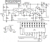
Right, so you have your Not-so-great VU meter circuit with everything attached, but not working all too well.

1) put a non-polarized cap on pins 4&5 - I've used a 563 (56n)
2) place a 1N4004 or similar rectifier diode forward to the signal input (pin 5)
ie:

(pin 5)------|<------(new signal input)

3) put a 1uF MKT/Ceramic cap directly after the diode. Add a 210k resistor (value not critical) accross the cap.

Now the signal input wire is connected to the other end of the cap.

And there you have it! much, much better performance!

Check out the Results on Youtube!

(btw, anyone know what the capacitor & resitor actually do in technical terms?)
 
hi Mike,
I think your previous circuit did not work properly because the pins on the BC548 transistor were backwards.

The 1uF capacitor at pin 5 to ground charges quickly through the diode then it discharges slower through the resistor so your eyes can see the peak. They are called a peak detector circuit. The diode should be inside the feedback loop of an opamp.

My Sound Level Indicator project also uses an LM3915 and the range extends to 50dB because it has automatic gain control. Its input is a microphone and its LEDs do what you want.
 

Attachments

  • Sound Level Indicator schematic.PNG
    Sound Level Indicator schematic.PNG
    64.3 KB · Views: 1,811
audioguru said:
My Sound Level Indicator project also uses an
LM3915 and the range extends to 50dB because it has automatic
gain control. Its input is a microphone and its LEDs do what you
want.

Why would someone put a AGC circuit in a VU meter ? :D :D :D

on1aag.
 
on1aag said:
Why would someone put a AGC circuit in a VU meter ? :D :D :D

on1aag.
The range of a single LM3915 is only 30dB. I used to have a VU meter with two cascaded LM3915 ICs with a range of 60dB which was too much.

My circuit with AGC detects a pin dropping on the floor of the next room or people quietly talking, and also shows pretty loud music.
 
What uses 320V?
The output of a microphone is only about 5mV to 50mV. The LM3915 can be powered from only 6V to 12V.
The voltage of LEDs is only a few volts, not hundreds of volts.

A VU meter for a microphone is simple. The microphone needs a preamp to feed a power amplifier or a recorder so the LM3915 uses the output of the preamp as its input.
 
This is my first post here so I hope it is appropriate. I have made several VU meters with LM3915, including one that is in the 3915 data sheet, and 2 or 3 more that is floating around on the internet, and to me the best VU meter schematic on the net, hands down, is (audioguru's) as posted in #2 of this thread. I have built 2 so far and they work as he described. Thank you very much audioguru! Now I have to make 2 more for the grand kids, for Christmas gifts.
I have been lurking here for a while and this is one of the best electronic forums I have been on, lots of good members, and good experienced people willing to help others. I look at this site almost every day, just to see if I can learn something new, and usually I do. Sorry for the long post. G.R.
 
Hi Garumel,
I am glad that you like my design.
Mine has been running continuously for 7 and one-half years and still works perfectly. The original 9V Ni-Cad rechargeable battery failed then was replaced by a modern Ni-MH 9V rechargeable battery but I rarely use the battery to power it.
 
Thanks audioguru, mine runs from a 120/12v plugin AC transformer, through a bridge and filter, and a LM7812 @ 12V DC, as I am driving 3 LEDs per output of all different colors, (3 blue, 3 red, 3green, 3 purple, ect), R7 is 910 gives about 14ma, and the LEDs are good and bright, and nothing gets hot or even very warm, even in bar mode. I like it, it works great, and on real loud sounds you can see it does kick down a notch or two to compensate. Thanks again.
G.R.
 
Status
Not open for further replies.

Latest threads

New Articles From Microcontroller Tips

Back
Top