Electro Tech is an online community (with over 170,000 members) who enjoy talking about and building electronic circuits, projects and gadgets. To participate you need to register. Registration is free. Click here to register now.
Welcome to our site! Electro Tech is an online community (with over 170,000 members) who enjoy talking about and building electronic circuits, projects and gadgets. To participate you need to register. Registration is free. Click here to register now.
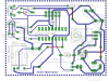
May be a bad idea to post the pour/fill in place. I do not see it. Take a look at the board and tell me if you can still get rid of it. I am not saying you can not but I can not see it right now.
Regarding the resistors. He can either cut the value in half and use two or replace one with a jumper.
AtomSoft: If you want to make changes please do it in Eagle or ask me to do them. If you use photoshop you could end up with problems that Eagle would have noticed. If you do not want the reset I can pull it out or you can choose to not populate it. As I said to Bill the LED resistor issue will not change the layout. If you removed the extra resistor you would need a jumper. I could pull the LEDs off the edge of the board and put them closer to the PIC and then using 1 resistor would not require a jumper. But I sort of like the LEDs where they are. Your choice. If the IR part is the same as the TSOPs I have you can mout it flat by bending the pins or leave them unbent and have it stick up.
A PCB is a lot like an oil painting. It is often hard to tell when it is done. This one should be close. The size is reasonable. The spacing is good. It passes all ERC and DRC checks. And it matches the schematic.
When I made the magic switchbox board I had to do it twice. The second time was to make it large enough so mear mortals could solder the thing. The contest sounds fun but I would rather do somthing useful.
At one point Cadsoft said you were not supposed to. I have copies of v4.16 and the current beta on my machine and both seem to work.
There are file format changes. Once you work on a file with the current beta (not sure at what rev number it happened) you can not go back to v4.16. And the beta is still a beta. Once in a while unexpected things happen, so far none have burned me.
Boncuk,
Had you posted first saying that you would do the board for Atomsoft I would have let you do so. Why are we still here?
This is Atomsofts board. I wanted to be faithful to his design, keep changes to a minimun. Atomsoft used a SMD regulator on the schematic but his intent was to use a through hole part.
sorry, Germans ave problems with the language barrier sometimes. I didn't get that. Sure, it's atomsoft's board. Therefor I didn't alter anything.
Anyway, my design shows that a double sided PCB isn't necessary using just one SMD component. Just mirror it and route like a through hole component. Saves three drills.
My board is still 100% single sided i used wires to jump from A--->B since it was only 3 .... i have to say thanks again i find it awsome that all you would help with this...
This site uses cookies to help personalise content, tailor your experience and to keep you logged in if you register.
By continuing to use this site, you are consenting to our use of cookies.

")