Continue to Site

Welcome to our site!

Electro Tech is an online community (with over 170,000 members) who enjoy talking about and building electronic circuits, projects and gadgets. To participate you need to register. Registration is free. Click here to register now.

  • Welcome to our site! Electro Tech is an online community (with over 170,000 members) who enjoy talking about and building electronic circuits, projects and gadgets. To participate you need to register. Registration is free. Click here to register now.

Making a Baseball Scoreboard

Status
Not open for further replies.

katq22

New Member
Hey guys,

New here and pretty green in electronics. I am pretty good at google and looking up information and putting it to use though. I can solder a kit together but don't really understand how most of it works works. But i am determined have patience and am willing to learn.

What I am trying to do is put a baseball scoreboard together. (i know you can buy them but where is the fun in that???)

It will need:
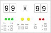
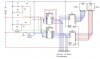
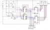
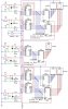
2 x 2 Digit 7 segment up/down counters that counts up on one button and down on a different button push.

1 x 1 Digit 7 segment up/down counter that counted 0-9 that counts up on one button and down on a different button push. ( this could also just cycle 0-9 then back to zero as 10 isn't a very high number to cycle if you made a mistake)

a row of 3 leds that light up one at a time per button push

a row of 2 leds that light up one at a time per button push

A reset button to reset the state of above two rows of led to be all off.

A row of 2 leds that cycle from off - 1 on - 2 on - off changing states on a button push.

That would all be in the controls of the unit and this would also output the bcd signals (to save wires) for the 7 segment led via a 25 pin connector to the actual scoreboard which will have large 7 segment displays and leds.

Basically what i need to know is how to make an up/down via push button circuit, then make that 3 times, and how to make the leds cycle again make it 3 times, the rest i should be able to work out. (i.e. connecting and running the bigger scoreboard.)

I have attached a pic of basically what I would imagine the controller to look like.

Even if you could point out some kits that do counters that would be great and i will see what we can do from there.

Many thanks in advance.

Ben
 

Attachments

  • Scoreboard - Controler.JPG
    Scoreboard - Controler.JPG
    25.8 KB · Views: 2,126
You may be able to buy just a simple 1-9 counter kit and add a few extra transistors to run a bigger display. You live in Melb. , Jaycar have a counter kit that you may be able to use.
 
The bit that has me confused and i cannot find anywhere is how to make it count backwards.

Take a look at the data sheets for 74LS191, 192 or 193. All are up-down counters, one of which might suit your purpose. There are probably cmos versisons also, but I don't have time to look them up.

Edit: That sounds too abrupt. Truth is, I have an 8:00 AM tee time!. First things first, you know?
 
Last edited:
Thank you everyone for the help. I will go to jaycar and check out there counter Kit. Will be purchasing the First past at least of the basket ball scoreboard kit, but i think it may be a bit advanced with wireless and everything plus I like the scorers to know the state of the scoreboard without having to turn around and look at it. And yes i think that the 74ls192 is what I will need to learn how to operate.
 
If you can find a multi direction counter kit, with a LEd display, you can still use the original LED display, you just need to add a few transistors to run the bigger board.
 
Well I only learnt today how to use Circuit Maker but here is my first effort. It works in simulator mode as a 2 digit counter. so I would make 2 of these for the scoreboard and a 1 Digit for innings.
 

Attachments

  • 2 Digit Counter.jpg
    2 Digit Counter.jpg
    53.3 KB · Views: 3,283
Could I make another counter circuit and use the bcd output to light the three lights for balls then reset on the fourth push? I have seen how it is possible stop the count short at say 6 for a timer. Like when it senses a signal on Q2 trigger reset for that chip. and for the strikes have the same setup and have the AND output reset for that chip. and a Master Reset button for both chips?

Here is a idea of what i would want, but i need the resets inserted.

Thanks for everyones help and ideas so far.

Ben
 

Attachments

  • Ball and Strike Counter.jpg
    Ball and Strike Counter.jpg
    35.2 KB · Views: 1,670
Could I make another counter circuit and use the bcd output to light the three lights for balls then reset on the fourth push? I have seen how it is possible stop the count short at say 6 for a timer. Like when it senses a signal on Q2 trigger reset for that chip. and for the strikes have the same setup and have the AND output reset for that chip. and a Master Reset button for both chips?

Here is a idea of what i would want, but i need the resets inserted.

Thanks for everyones help and ideas so far.

Ben

Two CD4017 would be ideal for balls and strikes. Tie outputs 1 and 2 to leds for strikes, 1,2 and 3 for balls, the next position would just be blank, then the next position returns to reset, which would actually activate the first LED again.

Make sure all your switches are debounced. There are many circuits you can use available here or by googling.

Good job.
 
I've gotten so used to the layout on one of the Baseball channels I think I would almost rather see that format used for a scoreboard...

Anyway, here's my idea using three chips in the controller and three chips in the signboard... Communications cable carries power and noise immune long distance capable RS-485 serial data from the controller to the remote scoreboard (design will support multiple remote scoreboards)...

Mike
 

Attachments

  • Scoreboard.PNG
    Scoreboard.PNG
    41.5 KB · Views: 1,075
Last edited:
Hey guys, still going with the project. Here is my latest version. I have made a couple of changes from the first circuit, such as make the first digit blank until in use. I think I have the debounce circuit correct but I don't really know. Could somebody please look it over for me. It no longer works in Circuit Maker due to the caps. I don't know what values I will need so if anybody could give me an Idea that would be great.

I really am having fun learning as I go. One more question Does the output from the 74ls48 need resistors inline with the seven segment LED?
 

Attachments

  • 2 Digit Counter 2.jpg
    2 Digit Counter 2.jpg
    55.5 KB · Views: 1,037
Ok a bit more research and I have come up with A 74LS14. I inserted that and now she works again. Still leaves me with the question of the values of the caps and resistors. I have no idea how to calculate them. (Even with the formulas, way to in depth for my feeble knowledge)
 

Attachments

  • 2 Digit Counter 3.jpg
    2 Digit Counter 3.jpg
    57.2 KB · Views: 2,779

Attachments

  • debounce.gif
    debounce.gif
    2.1 KB · Views: 628
Last edited:
I have setup the circuit as described but it does not work in circuit maker anymore. But if thats they way it should be thats all i care about. But what about the values of the Cap and resistors? I still can't get my head around how to work that out. I have read and re-read that web page but just can't work it out.

Thanks very much for the help.

Ben


I have added my file with my latest circuit. It has both home and away team scores and an inning counter.
 

Attachments

  • Baseball Scoreboard.jpg
    Baseball Scoreboard.jpg
    122.2 KB · Views: 2,402
I am not to familiar with circuit maker, but maybe it is not working correctly due to non values for the caps and resistors. Try putting in component values.
 
Last edited:
Last edited:
Thanks you so much for your help so far. you have very patient and helpful. Here is the circuit as I think it goes with all the switches and other components on it. I am not sure if what I have done with the ball/strike/out leds is correct. What I am trying to achieve is as each section is triggered on the 4017 it lights up One led as well as any leds that were before it. (I realize that a resister will need to be placed between the 4017 output and the led input)
 

Attachments

  • Baseball Scoreboard 2.JPG
    Baseball Scoreboard 2.JPG
    155.6 KB · Views: 1,161
Status
Not open for further replies.

Latest threads

New Articles From Microcontroller Tips

Back
Top