Continue to Site

Welcome to our site!

Electro Tech is an online community (with over 170,000 members) who enjoy talking about and building electronic circuits, projects and gadgets. To participate you need to register. Registration is free. Click here to register now.

  • Welcome to our site! Electro Tech is an online community (with over 170,000 members) who enjoy talking about and building electronic circuits, projects and gadgets. To participate you need to register. Registration is free. Click here to register now.

mains remote-alert question

Status
Not open for further replies.

electronic mind

New Member
the designer said:

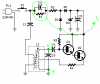
{{{Q1 and Q2 are wired as a Darlington pair to obtain the highest possible output from a Hartley type oscillator running at about 135KHz frequency. The 230Vac mains is reduced to 30Vdc without the use of a transformer by means of C1 reactance, a two diode rectifier cell D1 & D2 and Zener diode D3.}}}

now :
1- what is the use of the R and C in parallel
2- does this look like Hartley Osc. (nodes X ,Y should be connected to the input and the output of the amplifier)


to explain more about the circuit :

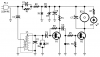
Pressing the pushbutton of the transmitter, a sound and/or light alert is activated in the receiver. The system uses no wiring or radio frequencies: the transmitted signal is conveyed into the mains supply line. It can be used at home, in any room from attic to cellar, simply plugging transmitter and receiver in the wall mains sockets. Transmission range can be very good, provided both units are connected to the mains supply within the control of the same light-meter.
 

Attachments

  • tx.png
    tx.png
    8 KB · Views: 439
  • rx.png
    rx.png
    6.8 KB · Views: 432
electronic mind said:
1- what is the use of the R and C in parallel

The resistor is there to discharge the capacitor, as it could be left charged to a high voltage.

2- does this look like Hartley Osc. (nodes X ,Y should be connected to the input and the output of the amplifier)

Looks fine - an oscillator requires positive feedback, and enough gain to over come any losses. From base to emitter of a transistor there's no voltage gain (only current gain), but the tap on the transformer gives the required voltage gain for it to oscillate.
 
Nigel Goodwin said:
electronic mind said:
1- what is the use of the R and C in parallel

The resistor is there to discharge the capacitor, as it could be left charged to a high voltage.


but combination of the resistor and the cap ,, what does it do??

i reduces the mains voltage i guess but how ?
 
it does not reduce the mains voltage.

The resistor is in parallel with the capacitor so it must sit at the same potential as the capacitor.

Now that cap will charge upto some voltage. When power is removed that cap will still hold that potential and will (very) slowly discharge. Now if you go and play around with the cct when you have just turned it off then you will get zapped

Now what that resistor does is when the cct is in operation it will dissipate some power (hence why burn-resistors like these are in 10's and 100's of kOhms), when power is removed the capacitor now has a path to discharge its stored charge, alot quicker then via its leakage.
 
I think we're assuming he knows more than he does?.

Simple answer:

The capacitor drops the mains voltage, by acting as a capactive dropper.

The resistor discharges the capacitor when it's unplugged for safety reasons.
 
Transformer

Hi guys,
What are the full specifications of that transformer? I've never used an IF transformer before and it seems there are a lot of parameters that need to be specified.
Any help would be useful!
Thanks
 
I should mention that all I found online was this:

https://www.redcircuits.com/Page56.htm

But it is still missing a lot of the IF parameters
Hi,
That TX and RX pair work ok in LTS simulation, but signal strength at the RX is very low.
I doubt that it would work over more than a few feet of mains wiring.
The TX power supply takes a few seconds to pump upto full 30V after the switch is operated.

Its just a simple 135KHz carrier On/Off system, no modulation, so its only action is,,, push/hold the switch on the TX, about 2 seconds later the RX beeper sounds.

IMPORTANT: both the TX and RX are not mains isolated,!
 
Last edited:
Thanks for the extra info.

I want to try this out (to see the maximum distance I can get in real life).

Is this pulse amplitude modulation?

What parameters do I need for the IF transformer? Searching online, I found a few IF transformers and they have things like turns ratio, impedance prim, Sec, etc. I'm not sure what these things mean exactly and how to figure out the required IF transformer from the schematic.

**broken link removed**
 
Thanks for the extra info.

I want to try this out (to see the maximum distance I can get in real life).

Is this pulse amplitude modulation? No.

What parameters do I need for the IF transformer? Searching online, I found a few IF transformers and they have things like turns ratio, impedance prim, Sec, etc. I'm not sure what these things mean exactly and how to figure out the required IF transformer from the schematic.
The transformers are standard Radio IF 455-465KHz, you could buy [once] 135KHz transformers, specially for this type of application
**broken link removed**

Lets know how it goes, DO NOT TOUCH or connect your MCU to the circuit when its connected to the 230v mains supply
 
Followup

So I emailed the owner of the website that had posted that circuit (https://www.redcircuits.com/Page56.htm) asking about IF transformers and this was their reply:

Hello,

thank you for your request.

The transformer used in the prototypes and suggested to the home constructors is a 455 to 470kHz IF (Intermediate Frequency) transformer. These transformer were used for many years in AM portable transistor radios that usually contain three items of this type.
At the time this circuit was designed and built (some 20 years ago) these transformers were available at electronics shops as spare parts for repairing those widely diffused radios.
At present it is very difficult to locate these transformers as AM transistor radios almost disappeared from the market in favor of FM or digital (Internet based) radios.
Therefore, the easiest way to find such a transformer is to disassemble an old AM transistor radio...

Hoping to have been of some help,

thanks for choosing RED Free Circuit Designs
 
hi,
I guess you are going to ask your friends for their old AM radio's.!

Try your local radio/TV repair man/shop.
 
Status
Not open for further replies.

New Articles From Microcontroller Tips

Back
Top