Continue to Site

Welcome to our site!

Electro Tech is an online community (with over 170,000 members) who enjoy talking about and building electronic circuits, projects and gadgets. To participate you need to register. Registration is free. Click here to register now.

  • Welcome to our site! Electro Tech is an online community (with over 170,000 members) who enjoy talking about and building electronic circuits, projects and gadgets. To participate you need to register. Registration is free. Click here to register now.

Mains Power Switch

Status
Not open for further replies.

drkidd22

Member
Hello,

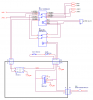
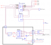
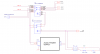
I'm trying to design a power switch for a project. The mains input is 240VAC and I've started with a few relays, e-off, power sw, and a temp switch in the loop. I want to use a mechanical single pole push button as the main power switch, but this way with the circuit I have if the e-off switch is engaged the main sw will remain closed, so no good. Then my second choice is to use a momentary sw, maybe capacitive or piezzo, but having a little issue designing around it. I will like to see what you think or other ways of doing this with minimal components as I have little space.
 

Attachments

  • mainspower.png
    mainspower.png
    28.9 KB · Views: 216
Last edited:
Comment: your in the US, and 240, so L1 and L2 should be the lines. Designations are L1, L2, N, G. 99% of the time neutral should not be switched.

Aside: I installed one piece or 3 phase 100 Amp piece of equipment that actually had a breaker in the neutral within the equipment.
 
Now that KISS mentioned it, Based on the drawing with L and N you only have 120VAC.

Additionally, there are not many 240VAC lightbulbs/indicators around. I know I have looked for them, they aren't common.
 
Sorry for the confusion. I edited the original post.
I have already sourced out a 240VAC bulb.
There is a circuit breaker and line filter on input line, just not shown for simplicity as I'm more interested in the logic of the on/off circuit. As I mentioned I'm trying to use a momentary switch or single pole push switch to control the on/off of the main relay.
 
I don't know what your device is, but I'd generally be happier with an explicit start/stop or something where the OFF direction is known. You could incorporate an ELM411 in the design. https://www.elmelectronics.com/ebench.html#Switches Although a TV might have the push o/push off mentality.

How to you want the device to behave after a power failure: 1) ON or 2) drop out

Impulse relays are a possibility if the swich needs to stay closed after a power failure. https://www.google.com/url?sa=t&rct...=3YrE3mPKMxc3Jf7LrBSHKA&bvm=bv.85970519,d.eXY
 
Last edited:
It looks like you want to use a SPST toggle switch for on and a PB switch for off as drawn. As drawn it won't work. You want to "latch" your mains relay. Also looks like you want to use low voltage DC for the control. Is this 240 VAC split phase where you have L1 & L2? I only ask because as long as neither L1 or L2 is neutral you are OK but in the US the NEC has issues with switching a "Neutral". You don't mention the load current? Reason I ask is because this can all be done with a single 3PDT (3 Pole Double Throw) relay or even a 3PST relay. Is this for any sort of industrial application? I ask industrial because where KISS mentions what happens on power failure? What do you want the circuit to do? Having power come up following a power outage gets into both NEC and OSHA stuff in any industrial application involving certain machinery.

Below is a simple latching relay circuit using a start and stop pushbutton. The start PB is normally open and the stop push button is normally closed. The additional relay contacts are not shown. The LED can be replaced with a PWR ON lamp.

Latching Relay Ckt.gif


If something like this is what you want I'll draw it for you.

Ron
 
Hi thanks for your response, yes it is split phase. The load can reach up to 25A. On power failure it should remain off until power switch is pressed again. The power switch type I'm trying to use is capacitive type https://www.apem.com/files/apem/brochures/switch-pushbutton-CP-ENG.pdf this is why I'm using low voltage control for relay. The idea is to use the capacitive switch as the means of latching the relay on or off, so this is the main power switch which also at the same time controls the 12VDC. The E-OFF switch shown in my drawing is just for emergency turn off and is not a means of always turning power off.
 
OK, great. That switch you linked to comes in two flavors. OFF-ON and OFF-MOM (Momentary) That can be worked into the scheme but which flavor will you be using and what DC control voltage? I understand the inclusion of an E-Stop (Emergency Stop Switch). The only issue I see is:

The idea is to use the capacitive switch as the means of latching the relay on or off, so this is the main power switch which also at the same time controls the 12VDC.

Circuits that work like this require constant DC power since you are opting for a capacitive touch switch. You can place a manual On-Off switch on your DC supply but that DC Bus needs power already present to function. Here are your switch specifications:

• Max. current/voltage rating : 200mA 24VDC
• Supply voltage : 5VDC, 12VDC or 24VDC
• Life expectancy : 50 million cycles
• Power consumption non-illuminated : 7mA
• Power consumption illuminated : 25mA
• Operating force : 0N
• LED state for output image option :
1 LED : the LED is ON when the output is closed.
2 LEDs : first colour is ON when the output is open. Second colour is ON
when the output is closed.
• Output type : NPN

Personally I wouldn't go with this switch and here is why:
This switch should not be used
in safety applications.


Anytime an E-Stop is involved you want to keep things as straight forward and foolproof as possible. The switch output type is Open NPN which is like an open collector NPN transistor but they seem to be using an N Type MOSFET. As drawn in the data sheet I don't see any flyback diode protection for the MOSFET? Anyway, when switches like this fail they fail shorted 99% of the time, the MOSFET shorts and unless you have a mechanically latching E-Stop (large red mushroom head with a twist lock normally closed) you are in trouble. This is why the data sheet mentions not using this type switch in any safety application.

When it comes to applications like this I suggest keeping things conventional. You can still have a nice panel and still have pretty LED lamps but keep the relay latching simple just using mechanical switches of the push button type. Thoughts?

Ron
 
Tomorrow morning I'll draft up a drawing of how I would go about it, then you can see what you think and or modify as you like.

Ron
 
Here is how I would do it, there is no BOM (Bill of Materials) on the drawing as I have no idea who you buy parts from. The On/Off LEDs do not reflect a series resistor. Years ago I got sick and tired of buying T-1 3/4 bayonet base incandescent lamps for 24 & 28 VDC circuits. Damn lamps kept burning out in 24/7 service. Dialight and Eiko manufacture perfect replacements that don't fail. While expensive compared to the cheap lamps I love the things. Standard bayonet base so they were a direct replacement. The Start and Stop are standard PB Momentary switches. Any E-Stop(s) just run in series with the Stop switch. Since you mention 25 Amp I would use a 30 or 40 amp rated contactor with AWG 10 or AWG 8.

240 VAC Latch.png


Ron
 
Hi thanks for the drawing. I you may have misinterpreted some of my explanation. I want to use a single push button for start and stop.
 
Can be done using a flip flop. Push for On, push again for Off. Going to add a few parts but can be done. Give me some time and I'll get a drawing of what I am talking about. The downside is working around the E=Stop and relying on the mechanical break and remain open.

Ron
 
Back to the ELM411 IC which is just a PIC processor with the toggle code.

Ron: I made a bunch of panels made with a few hundred ALCO switches and they changed the design so it trapped the heat (O ring on the lamp) and broke the lens. I was a shame they lost a customer. I went to IDEC and LEDS Had to. Never regretted IDEC.


I loved those things. The ones that I swapped had been in service 5 to 8 years when I retired. While expensive in the ititial outlay they do pay for themselves. Good stuff! :)

Ron
 
Hi thanks for the drawing. I you may have misinterpreted some of my explanation. I want to use a single push button for start and stop.

Then, all things considered I would use the switch you linked to in the 24 volt Off-On configuration. I could build a flip flop circuit but it would be the same thing pretty much with the same weakness. Just make sure there is a good and reliable mechanical latched open E-Stop. Personally I wouldn't do it that way but you know what is best in your design as to what things do.

Ron
 
Ok guys I had some time to play a little more with this and still can't find easiest way possible to get this going. As simple as this is the only way to turn it back off is with the e-off switch or when mains power is turned off. If anyone has any other suggestions how to use the same momentary switch to turn it back let me hear it. I could always use use 2 momentary switches as mentioned before, but I want to limit it to 1.
 

Attachments

  • AC Control.PNG
    AC Control.PNG
    20.3 KB · Views: 195
With this one I tried using a Latching relay, but the only issue is if mains is removed they maintain previous state and once mains is restored power will come back on, ideally should remain off until SW5 is pressed again. I could also move SW3 to output of U1, but would still have same issue.
 

Attachments

  • AC Control2.PNG
    AC Control2.PNG
    28.9 KB · Views: 197
Status
Not open for further replies.

Latest threads

New Articles From Microcontroller Tips

Back
Top