Continue to Site

Welcome to our site!

Electro Tech is an online community (with over 170,000 members) who enjoy talking about and building electronic circuits, projects and gadgets. To participate you need to register. Registration is free. Click here to register now.

  • Welcome to our site! Electro Tech is an online community (with over 170,000 members) who enjoy talking about and building electronic circuits, projects and gadgets. To participate you need to register. Registration is free. Click here to register now.

Magnetic Pulser

Status
Not open for further replies.

Narajin

New Member
Hi everyone,

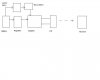
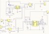
I made a circuit composed of a class d amplifier driving a magnetic coil that pulses at 21 hz. It has a 3V battery as a power source. This works fine.

When I extend my design to have a 5V regulator, the magnetic pulses gets screwed up. I check the magnetic pulse outputs and it is distorted. The regulator output has spiked voltages in intervals. So I suspect having a regulator has something to do with this problem.

I tried putting a diode in series, output capacitors (up to 100uF) on the regulator, zener doide in parallel. All to no avail.

All I need to do is to make the regulator act like a battery. As with the battery I did not have any problems. Any suggestions?
 
Which regulator? What's your supply voltage to it? How much current does the magnet use? Heatsink on the regulator?
 
Ok. Sorry about that.

Current with battery only should be about 10mA-50mA (depends on the magnetic coil I use). With regulator it is about the same (might be a few mA higher vs just battery). On the average about 40 mA.

Regulators I tried and used are MIC5205-5.0YM5 TR (150mA), MIC5207 (180mA), and a 7805. I vary my supply to it about 5V-12V (I designed for 7.2V).

No heat sink on regulator. Doesn't need it.

It has something to do with the inductive load screwing up the power. I put a diode to isolate the regulator but no avail.

Help please.
 
Its to track something. I followed the data sheets on it and it worked fine with the battery as a straight power source.

I uploaded a block diagram.
 

Attachments

  • block diagram.JPG
    block diagram.JPG
    13.5 KB · Views: 386
Try posting the schematic. Maybe someone will see something wrong that isn't apparent on the block diagram.
 
I don't see why you are having problems with the regulator, but it appears you are running digital signals into the analog inputs INP and INN. I don't see how you can get PWM this way. Are you not using PWM?
 
Pulse width modulated? I think the amplifier can take in digital signals. It works without the regulator.

HHO generator? Sorry, its new to me.

Any simple tricks to quieting this regulator?

Forgive me if I am wrong. My theory is that somehow the inductive load has voltage backflow and it flows all the way back to the regulator.

With a battery source, there is also an inductive effect but the voltage spikes aren't as immense as with a regulator in between.
The TPA2000D1 is a pulse width modulator. It produces PWM at the output in response to analog signals at INP and INN.
I still don't know why your system doesn't work with a regulator. I would start by connecting 0.1uF caps from input and output of the regulator to ground. I would also connect a large cap (100uF or more) from the regulator output to ground.
What is the inductance of your load? What is the duty cycle?
 
In reference to my first post, I already did connect 100uF output cap. As for input I think I tried 1 uF cap. All it did was lessen the voltage spikes, but my receiver still received crap.

As for the analog input, does it matter whether it gets an analog signal (I'm assuming a sine wave) versus digital (square wave)? I think as long as there's an input the amplifier doesn't really care.

I thought about that at one point and built it anyway and it worked. I don't see any reason why a regulator would screw things up.

For duty cycle, I designed it to pulse at 21 hz.

So thats 23.8ms HIGH and 23.8ms LOW. Or 50% duty cycle. As for inductance, I use many different coils each having the same effect. This particular one I use for testing is 233.8 mH and resistance 10.6 ohms. But the coils I've used can range from 71.24mH to 441mH and resistance from 4.7 ohms to 50 ohms.
 
Last edited:
The datasheet for the TPA2001 shows that the load current is zero when the input is zero. See Fig. 10. Most voltage regulators have a minimum load requirement. Try putting a 470 ohm load (to GND) on your regulator and see if it fixes your problem.
 
MIC5207 or MIC 5205 has a no load stability which means it should work and remain stable with no load.

However I will give it a shot and let you know. Although even if it fixes it, since it will be extra power drain it will not really be a fix application wise. My application requires conserving battery life and making it pulse as long as possible.

Thanks for the suggestion.
 
If you are switching 10V p-p across 233.8mH + 10.6 ohms, the peak current from your regulator will be approximately 232mA. The MIC5205/5207 is only specified to 150mA.
 
How did you get 232mA?

Design ultimately should be for 7.2V. I was testing for 5V-12V but even at below 10V it didnt work. Current never went over the limit of 180mA but there might have been some spikes which weren't apparent in the initial current readings.
 
Status
Not open for further replies.

Latest threads

Back
Top