Continue to Site

Welcome to our site!

Electro Tech is an online community (with over 170,000 members) who enjoy talking about and building electronic circuits, projects and gadgets. To participate you need to register. Registration is free. Click here to register now.

  • Welcome to our site! Electro Tech is an online community (with over 170,000 members) who enjoy talking about and building electronic circuits, projects and gadgets. To participate you need to register. Registration is free. Click here to register now.

magnetic card head reader from cassette player help needed

Status
Not open for further replies.

Andronikov

New Member
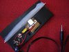
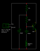
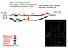
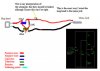
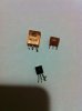
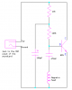
I am working on a project for school show and tell, I found a really cool project that I want to build, it's a magnetic stripe reader made from a mono cassette players magnetic head and uses sound, so there is an amplifer that I am trying to build that will amplify the sound enough to get a reading, so we can scan all our student id's, and I just started getting into electronics, I really love this new world but I'm so lost when reading schematics so if anyone can please help me!! I already have the schematics of different types, then I drew a picture representing how I inturpreted the schematic (how I connected all the wires) there are two pictures here of other peoples designs, I just need something simular to that, I want to be able to make this portable so I can connect in the jack to handheld recorder, then plug in the recorder and remove the sound file from it on the computer and get the information that way, instead of just plugging it into the sound card on a computer, because I dont have a laptop to plug into so I will just take it over to the teachers computer to remove the files and show everyone how it read.
**broken link removed**
http://images.elektroda.net/57_1306152784.png
http://images.elektroda.net/40_1306152784.jpg
http://images.elektroda.net/62_1306152784.jpg
http://images.elektroda.net/55_1306152784.jpg
 

Attachments

  • cardreader.jpeg
    cardreader.jpeg
    96.7 KB · Views: 1,379
  • cardreader_schema.png
    cardreader_schema.png
    2.2 KB · Views: 1,173
  • myscheme.jpg
    myscheme.jpg
    65 KB · Views: 514
Firstly it is good you have done your homework and provided all the information.

You do have troubles in your circuit drawing, and have several things wrong.
The capacitor (470n) you have attached to the mag head should not be polorised with +/- and this capacitor connects to the base pin of the transistor where you have a ? mark, the 120k resistor also connects to this same pin.
The other leg of the 120k resistor connects to the + leg of the second capacitor (100uF) the 15k resistor also connects to the + leg of the second capacitor.

You will also need to find which is the emitter, collector, and base (EBC) pins on the transistor you are using as all transistors vary in the location of these pins.
If you have trouble list the transistor you have here and someone will tell you which pin is what.

The hand held recorder you intend to use is what exactly?

Pete.
 
confused

Ok I redid the drawing but I'm confused, you mentioned a 2nd capacitor but in the drawing there is only 1 capacitor and 1 transistor?
Also is it ok to use a 470uF instead of a 470nf I also have 100uF capacitors could I use one of those? I have allot of different transistor models, one is a C1815 transistor and the others, I took a picture as instructed.
Please let me know if I made it better or worse :-S:confused:
 

Attachments

  • myschematic2.jpg
    myschematic2.jpg
    65 KB · Views: 1,964
  • IMG_0704transistors.jpg
    IMG_0704transistors.jpg
    1,002.4 KB · Views: 436
oh and I wanted to remove the audio jack because that was for plugging in a computer, and just connect it into the microphone area on the sound recorders circuit board, after removing the one that was there. There is a positive and negative area for the wires so I just pulled off the little microphone on the board and put the wires in and soldered it on. The recorder I am using is a $30 Olympus VN-6000 1GB Digital Recorder from radio shack I had laying around.
 
Why is your schematic a backwards negative image with a black background??
I fixed it.
 

Attachments

  • transistor amplifier.PNG
    transistor amplifier.PNG
    4.2 KB · Views: 503
humm

The schematic you fixed is not my schematic, it's the one that I can't understand, my schematic is the hand drawn one with wires only, I can't read that schematic, can you fix my schematic? that would be perfect!!!!!!!!!!! and exactly what I need, please!!! :D:D:D
 
I have done the conversion from your backwards negative image to positive today on another website. Except now it was saved as a fuzzy Jpeg file type. Here is the way it should be saved and posted:
 

Attachments

  • transistor amplifier.PNG
    transistor amplifier.PNG
    4.2 KB · Views: 389
Oh. You made a completely wrong wiring diagram instead of a schematic. Maybe you should arrange flowers instead of doing electronics.
 
I know it's wrong, that's why I'm here asking for help! You would rather make fun of me then help me?

You posted a schematic and your wiring diagram. They are completely different, can't you see? The circuit is extremely simple so why can't you make it correctly?
 
Don't let Audio McDuck get to you. Just ignore him, like a lot of us around here have learned to do. Please keep posting.
 
isnt there anyone else who's not a complete ahole who can help me?

The problem here is that you can't relate to or understand schematics at this point. That is not a bad thing as being able to read and understand schematics takes time beginning with the symbols. Since you don't understand the schematic you posted you are trying to rely on basic pictures. I don't have the tools here to make the schematic into a diagram/picture you may be able to relate to. You don't want a schematic symbol of the transistor denoting the emitter, base and collector leads, but rather you want a picture showing wires and where they go. Maybe someone here can give you a cartoon to work from.

Ron l
 
Well, without being an a-hole about it (I hope!), I have to tell you that you really need to learn to read schematics.

The good thing is it's not hard at all. Not hard like learning calculus or double-entry bookkeeping or stuff like that.

The schematic looks pretty much like the actual physical circuit you'd make, except that it uses standardized symbols instead of pictures or cartoons.

Most parts are pretty obvious. Some, like transistors, aren't, because the pins on those devices aren't marked (E=emitter, B=base, C=collector). However, you can get that information easily enough from datasheets (something else you should become familiar with). F'rinstance, from the 2N3904 datasheet:

**broken link removed**

This tells you which pin is which and how to connect to the actual physical device.

If you have any specific questions about your circuits or schematics, ask and some of us will be glad to help you.
 
Ok, lets try a block schematic and see if you understand this, you would wire the components together just the same as the lines are drawn between them.

As for your question earlier about changing capacitor values the short answer is NO as you have no idea what you are doing and if you want the circuit to work you need to stick with the component values shown.

And secondly there is 2 capacitors in the circuit, not 1 as you seem to think. (look again)

Capacitor #1 is not polorised and can go either way around and will work, capacitor #2 IS polorised and will have ----- marked on the package next to 1 leg and this is the negative leg that is connected to ground.

Pete.
 

Attachments

  • Block Schematic.pdf
    8.2 KB · Views: 409
Last edited:
Hello, thank you all for your help, thank you very much.
The block schematic helped me to understand the regular schematic and see how simple it really was, I heard from someone that I need a power source, but wont the digital recorder be as a power source? Or how would I add a power source to make all this work? I'm sorry I'm so new at this and I am very happy for all your help I'm improving. Thank you.
 
Status
Not open for further replies.

New Articles From Microcontroller Tips

Back
Top