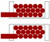
I want to wind magnet wire on a bobbin. When I make the first layer, all is fine. When I am winding on top of the existing wire layer, I get a bump because I am changing the pitch when I change directions. I am using small 28 to 40 gauge wire. Is it possible to get consecutive smooth layers without paper?
Continue to Site
")