Continue to Site

Welcome to our site!

Electro Tech is an online community (with over 170,000 members) who enjoy talking about and building electronic circuits, projects and gadgets. To participate you need to register. Registration is free. Click here to register now.

  • Welcome to our site! Electro Tech is an online community (with over 170,000 members) who enjoy talking about and building electronic circuits, projects and gadgets. To participate you need to register. Registration is free. Click here to register now.

LTSSPICE Question

Status
Not open for further replies.

3v0

Coop Build Coordinator
Forum Supporter
I am learning to use LTSPICE.

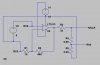
For kicks and giggles I started with the MCLR generation section of the Stoltz ICD2. Got that working using generic PNP and NPN transistors.

Now I want to try Stoltz's opamp version of the same.
I did not see the LM358 opamp it in the list. There are several generic/universal opamps. Should I use one of these or hunt for the part somewhere?

Is there some way to have the schematic redrawn with the voltages shown after a run. It would be easier to use then the text list of nets.
 
The LM358 is different from ordinary dual opamps:
It is low power (the first one) so its supply current is low.
2) Its minimum supply voltage is 3.0V.
3) Its output goes to the negative supply voltage if its sinking load current is low.
4) Its inputs work well at the negative supply voltage.
5) It has crossover distortion.
6) Its max frequency for only half the max output voltage is 6kHz.
 
3v0 said:
Now I want to try Stoltz's opamp version of the same.
I did not see the LM358 opamp it in the list. There are several generic/universal opamps. Should I use one of these or hunt for the part somewhere?
You can run the simulation with an LT1013. It's a dual precision op amp that works with single supply and it can be used as a replacement for the LM358.
 
I suspected that was the case.

Found several places on the net that have models for the LM358 but am unsure of how to use the files so LTSPICE can see them. So far the tutorials I have looked at do not go into adding new components. A pointer to one that does would be great.
 
LTspice is fantastically great (IMO). Congratulations.

Here is a sort of "master list" of spice models on the web:

**broken link removed**

Using most P-Spice-type models with LTSpice is easy. They're usually subcircuit-type models. For an opamp model, there's already a handy existing symbol you can use, "opamp2" in the Opamps library. Plop it onto your schematic, right-click on it, click in the "Value" column in the "Prefix" row and then enter X in the "edit box", above the table (X tells the program it's a sub-circuit model). Then click in the "Value" column of the "Value" row, and enter the subcircuit name (e.g. LF358), as it appears in your model file. Then, on your schematic, place a spice directive (with the .op button) like .include yourmodelfilename.sub, where sub is whatever the filename extension is (Often, it's sub, but needn't be.).

The LT-SPICE Yahoogroups group is truly excellent. The people there are amazing. Be sure to download the library file that lists all of the library files, and the one that lists all of the message topics. Then you can search through them with Wordpad, or whatever, which is often more productive than doing it only on line, although it WOULD be nice to have the full text of all of the messages, as well, since yahoogroups' message-searching is so clunky.

-----------------

A few things that might be good to learn sooner rather than later, just off the top of my head, and in no particular order:

You can right-click on a plot and select "Add Plot Pane", to have more than one simultaneous plot. It's handy for plots with way-different scales, et al. You can click anywhere in a plot pane and then the next thing you click on in the schematic will be plotted in that pane. You can also just drag a plotted quantity's label from wherever it is to anyplace in a plot pane you want to move it to.

You can drag a rectangle around any part of a plot, to make it fill the plot pane, i.e. magnify portions of a plot, repeatedly if desired. You can also drag rectangles to measure things. The deltas are displayed in the bar at the bottom.

You can Alt-Leftclick on any device, to plot its total power dissipation!

You can right-click on any plot label and enter ANY ALGEBRAIC EXPRESSION to be plotted! And if you enter a voltage divided by a current, the plot units will be shown as Ohms, for example.

After a run is stopped, you can Ctrl-Leftclick on any plot label and it will INTEGRATE that plot, for you, giving RMS, AVG, and/or Integral values, as appropriate. Note that it will integrate only the currently-visible window. So if you only want to integrate over part of a plot, you can drag a rectangle around the part you want, so it fills the window. (FFTs can work that way, too, but give you a choice of either way.)

Always un-check the three compression options, in the Control Panel, or, better yet, include .options plotwinsize=0 on all of your schematics, to turn off compression.

(Almost) Always specify a min timestep, for transient runs.

You can use .WAV files, as both inputs and outputs!!! The possibilities are staggering...!

Learn to make your own subcircuits, so you can have hierachical schematics. It's great, especially for larger projects. You can eventually have what amounts to a block diagram, with just your interconnected subcircuit symbols, and can then "drill down" to wherever you want, in the hierarchy. It's easy. If you have a schematic that will be part of a larger schematic, and you have labeled the inputs and outputs, just create a symbol for it, with the same name as the schematic, and put whatever inputs and outputs you want, in the symbol. Then it can be added to any other schematic, using the regular "add component" button, by using the "Top Directory" box at the top of the "add component" dialog to get to the "personal" library of subcircuits in the current folder. And whenever you're in a schematic that has a subcircuit symbol, you can right-click on the symbol and select Open Schematic, if you want. Also, if you go into the control panel and select all of the Save... voltage and currents, you'll be able to plot from such schematics just like from the top-level one.

The MEASURE commands are too cool, and very powerful. There are examples in the Files section of the LT-SPICE group.

The .STEP commands are powerful. You can set a component's value (by right-clicking on it) to, say, {C}, and then use a .STEP command such as .STEP {C} list 2.2p 3.3p 4.7p 10p to run a simulation for each value of C in the list, or something like .STEP {C} 10p 1010p 100p, to run sims with C from 10p to 1010p in 100p steps. The plots will be plotted together, with different colors. Right clicking on the plot pane and selecting Select Steps will show you which color is for which stepped value. You can also nest the step commands, at least two levels deep.

To get all of the node voltages, etc, like you mentioned, I think you just do a .DC op pnt analysis, and a window pops open with all of the voltages etc, which you can copy to the clipboard with Ctrl-C, if you want. Then, whenever you pass the cursor over a node, the DC operating point is displayed in the bar at the bottom of the screen.

Oh, make sure that you set up your Keyboard Shortcuts, in the Control Panel!!

I guess there's so much more that I might as well just quit, for now. And I'm sure that I haven't thought of some of the really good ones, here. I'll post again, if I run across them.

Have fun!

- Tom Gootee

**broken link removed**

-
 
Last edited:
Tom,

Thanks for all the info.

I need to run through a few tutorials. But if someone sees a obvious blunder here please point it out. Please do not spend time on this unless you enjoy doing so.

I created the opamp version of the MCLR circuit usng the LT1013 and ran it using .op In the status at the bottom it displays "Stepping 98.9466% Step Size =..".

Thinking this is because the opamp has feedback from output to the inverting input. Never get to a steady state using .op. ??

The log has a hint about using .option noopiter but it did not change anything that I could see.

First few lines of log
Code:
Circuit: * C:\Program Files\LTC\SwCADIII\OpAmp.asc

Early termination of direct N-R iteration.
Direct Newton iteration failed to find .op point.  (Use ".option noopiter" to skip.)
Starting Gmin stepping
Gmin = 10
Gmin = 1.07374
Gmin = 0.115292
Gmin = 0.0123794
Gmin = 0.00132923
vernier = 0.5
vernier = 0.25
vernier = 0.125
vernier = 0.0625
vernier = 0.03125
Gmin = 0.000544452
vernier = 0.015625
vernier = 0.0078125
vernier = 0.00390625
vernier = 0.00195313
vernier = 0.00260417
Gmin = 0.000542771
vernier = 0.00347222
Gmin = 0.000538666
vernier = 0.00462963
vernier = 0.00617283
Gmin = 0.000532009
 

Attachments

  • OpAmp.asc
    1.7 KB · Views: 335
  • OpAmp.jpg
    OpAmp.jpg
    28.5 KB · Views: 930
Last edited:
Nice catch, Ron! Every once in a while, I STILL do that to myself. Not connecting power to some opamps is another one that still gets me, occasionally.

3v0,

You probably already know all of this. But... With other convergence problems, it's sometimes beneficial to un-idealize certain types of components. I always add at least a small amount of ESR to caps, and DCR to inductors, for example.

Other times, you might have to go into the Control Panel's Spice tab, and try the Alternate Solver, and/or mess with Gmin, Trtol, etc etc.

Mike (Englehardt, of LTC, LT-Spice's author, aka Panama Mike) has also added access to a few special-case convergence aids, such as tseed, which have been discussed and archived in the yahoo group.

Note, too, that I am so far from being an LTspice expert that I probably shouldn't be trying to tell anyone anything about it. The LT-SPICE Yahoogroup is, by far, your best source of information and help, etc. Of course, if I DO happen to think I know something about a question you or anyone else has asked, I will gladly share what I think I know.

- Tom Gootee
 
Last edited:
I have a long way to go till I understand half of what you just said. I installed the package and was lucky to have my first attempt work. Not quite so lucky with the 2nd but with a bit of help that worked too. Now that I have had my fun I suppose its time to RTFM.

Still have to figure out how to install/use all the components/model/whatever floating around out on the web. Seems sort of weird that they do not all have a single file type.

Life is good.:D
 
3v0 said:
I have a long way to go till I understand half of what you just said. I installed the package and was lucky to have my first attempt work. Not quite so lucky with the 2nd but with a bit of help that worked too. Now that I have had my fun I suppose its time to RTFM.

Still have to figure out how to install/use all the components/model/whatever floating around out on the web. Seems sort of weird that they do not all have a single file type.

Life is good.:D

With LTspice, I basically have only learned what I have needed to learn, which was done AS the needs arose, except for what I've picked up by reading the emailed digest of message traffic from the LT-SPICE group.
 
The manual for LTspice isn't so great. Most circuits on the net are 'sub circuits' which basically means you include the file and 'map' the nodes in that sub circuit to the nodes in a 'symbol' (a graphic on the screen which you can even make your own custom version of) Most subcircuits 'map' onto things like basic opamp or transistor symbols, some sub circuits (Mostly those on the lt-spice users group) will come with a symbol to use, as symbols and schematic entry aren't native to Spice itself.
 
Those are good things to play around with, browse a few very basic sub circuit models on the net, edit a few symbols and try to make your own, or upgrade existing symbols (It's basically a line drawing version of paint) What's you get down to the real meat an potatoes of LTspice, or any spice simulators, it's just a basic text editor with 'fucntions' to describe anything involving electricity (some physical systems as well)
 
Last edited:
I'm no ltspice expert but I've learned a lot if you've any question you think I might be able to help with lemmi know.
 
3v0 said:
Still have to figure out how to install/use all the components/model/whatever floating around out on the web.

If you have the model of an LM358, try this: save the file in the "sub" folder, as "LM358.sub". Choose and place an "opamp2" and enter "LM358" in the "Value" field. Add the directive ".LIB LM358.sub" to your schematic and try running the simulation.
 
eng1 said:
If you have the model of an LM358, try this: save the file in the "sub" folder, as "LM358.sub". Choose and place an "opamp2" and enter "LM358" in the "Value" field. Add the directive ".LIB LM358.sub" to your schematic and try running the simulation.
This works for almost any subcircuit. For some, you will have to copy the subcircuit from a web site or forum posting and paste it into notepad. Save it (as eng1 says, in the "sub" folder) as file type "All files". The caveat here is that it if you accidentally (or intentionally) save it as type "*.txt", it will actually get saved as "LM358.sub.txt". To see this in Windows Explorer, you need to go into the Tools dropdown menu, select "Folder Options", select the "View" tab, and uncheck the box for "Hide extensions for known file types". The saved file must be renamed as "LM358.sub" (or whatever".).
Another caveat is that the subcircuit needs to be given the same name in the value field for opamp2 as it has in the file. For example, the National LM358 file "LM358.mod" names the subcircuit "LM358/NS". You can either enter this in the "opamp2" field, or you can edit the subcircuit name in the file and re-save it. You may also have to rename the subcircuit name in the ".ends" statement if it occurs there.

You can import other types of subcircuits and use them with the DIP14, DIP8, etc., symbols in the "misc" folder. I have also edited DIP8 and created and saved DIP3 (for voltage regulators, etc.).
 
hi all,

i am new to ltspice, can somebody please guide me how to use a bridge rectifier in ltspice ,i have downloaded scr model but its not working ang gives the error when i start to simulate

unknown subcircuit called in xu1 n002 n003 0 scr1

Please help me out to solve this issue. Thanks
 

Attachments

  • SCR1.asc
    861 bytes · Views: 309
  • SCR.asc
    2.8 KB · Views: 236
Status
Not open for further replies.

Latest threads

Back
Top