Continue to Site

Welcome to our site!

Electro Tech is an online community (with over 170,000 members) who enjoy talking about and building electronic circuits, projects and gadgets. To participate you need to register. Registration is free. Click here to register now.

  • Welcome to our site! Electro Tech is an online community (with over 170,000 members) who enjoy talking about and building electronic circuits, projects and gadgets. To participate you need to register. Registration is free. Click here to register now.

LT Spice

Status
Not open for further replies.

ronv

Well-Known Member
Most Helpful Member
I'm new to LTSpice and now need to add some models. I've googled my brains out bit am still confused on how to add models. Mike helped me add a regulator, but when it came time to add a zener it became clear I didn't really understand how to do it.
What I would like to propose is that we come up with a beginners procedure for adding models. I would be happy to be the beginner to test it.

Any experts out there that would help?

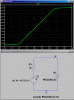
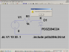
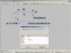
We could start with my latest attempt: I downloaded a PD3Z284C24 Zener from diodes Inc.
 
Have you solved the unzip problem?
 
Here is the step by step process that worked for me:

1. Copy and paste the PD3Z284C24 Spice subcircuit from **broken link removed** to a generic text editor window, like Notepad. Save the file in your working subdirectory as PD3Z284C24.txt.

2. Create a LTSpice schematic. Using the little AND gate icon submenu, select a ZENER diode from the predefined list of symbols and insert it into the schematic. Add a 0V voltage source V1 for simulation stimulus, and a 1K resistor between the positive terminal of the supply and the cathode of the Zener. Ground the anode and the negative terminal of the supply. Name the node connected to the cathode of the Zener K.

3. If you right mouse click on the predefined Zener symbol, you normally could select a diode (including some Schottkys and Zeners) from a standard diode library. Since the model for the PD3Z284C24 is in the form of a .SUBCKT (not a diode .MODEL), we will borrow the Zener symbol, but hook it to our saved text subcircuit. Do this by using a CTRL-Right mouse click with the cursor over the Zener symbol.

4. You will see a "Component Attribute Editor" window pop up. First place the cursor over the first attribute Prefix Value "D", and double click to select it. Change it to X instead of D. Change the fourth attribute from D to PD3Z284C24, and click OK.

This modifies the first attribute of the symbol to link up to a SUBCKT instead of a library containing models (X vs the D) and specifies that there needs to be a ".SUBCKT PD3Z284C24" in an eventual .INCLUDE file.

5. Add a .INCLUDE PD3Z284C24.txt directive into the Schematic page.

6. Finish the schematic by selecting a method of analysis (I used a DC SWEEP ".dc V1 -10 35 0.1",

7. FILE SAVE-AS the schematic and force it to be written to the same subdirectory where you originally saved PD3Z284C24.txt.

8. Then simulate.

9. Your results should look like this:
 

Attachments

  • Zener.png
    Zener.png
    27.8 KB · Views: 722
hi ronv,
Download the free IZArc unzipper, it handles most zips.
**broken link removed**
 
Fun?

Thanks Eric for the zipper. I tried it on your previous post and it seems to work!

On to the diode-- I clicked on the link to diodes inc. and got a warning from my virus detector -- trojan.js.redirector.bu so I went to diodes inc. and copied the file to notepad without issue.
Made a pass following your directions as best I could. Here is where I think I went wrong:
Not sure about working directory so I used the spice library sub directory.
Not sure if I should use a specific diode (say 1N750) or the generic zener. I think I tried both.
When I try to simulate it I get an error about inductance. Have no idea where that may have come from.
Below is my edit of the procedure:

Go to the manufactures site and find the model you are looking for.
Copy the model to note pad and save the file with the parts part number as a text file (.txt) in LTC\LTCSPIVEIV|Lib\sym
Working subdirectory??
Start a new Spice schematic.
Using the AND gate (Component) icon submenu, select a ZENER diode from the predefined list of symbols and insert it into the schematic.
Using the same submenu add a 0V voltage source V1 for simulation stimulus, and a 1K resistor between the positive terminal of the supply and the cathode of the Zener.
Click the text icon, select the spice directive circle and lable the cathode with a K.
Since this model for the PD3Z284C24 is in the form of a .SUBCKT (not a diode .MODEL), we have borrowed the Zener symbol, and will hook it to our saved text subcircuit. Do this by using a CTRL-Right mouse click with the cursor over the Zener symbol.
You will see a "Component Attribute Editor" window pop up. First place the cursor over the first attribute Prefix Value "D", and double click to select it. Change it to X instead of D. Change the fourth attribute from D to PD3Z284C24, and click OK.
This modifies the first attribute of the symbol to link up to a SUBCKT instead of a library containing models (X vs the D) and specifies that there needs to be a ".SUBCKT PD3Z284C24" in an eventual .INCLUDE file. Add a .INCLUDE PD3Z284C24.txt directive into the Schematic page.
Click the text icon, select the spice directive circle and and type .Include PD3Z284C24.txt and ok. Add this to the schematic.
Finish the schematic by selecting a method of analysis from the “Edit, Spice analysis icons(I used a DC SWEEP V1 -10 35 0.1) V1= source to sweep, 10 the start value, 35 the stop value. .1 the increment. These values should be within the parts specs.
FILE SAVE-AS the schematic and force it to be written to the same subdirectory where you originally saved PD3Z284C24.txt
See attachments for more on the error and the directory.
Thanks for all the help!
 

Attachments

  • zd2.PNG
    zd2.PNG
    42.2 KB · Views: 473
  • zd.PNG
    zd.PNG
    43.5 KB · Views: 481
  • zd1.PNG
    zd1.PNG
    54.5 KB · Views: 521
Your schematic page is missing a ground on the negative side of the voltage source/anode of the zener.

It is bad practice to place user created files in the LTC subdirectories.

I would create a "MyCircuit" directory under your "My Documents", and move your files there. Initially, there need be only two files: xxx.asc, and one to match what is in the .INCLUDE directive. When you simulate, other files will get created, including xxx.raw, xxx.net, xxx.log.

Your system hides file extentions; I would make them visible via the System setting: Folder Options: uncheck "Hide extentions for known file types".
 
Last edited:
Gotta aways have a ground. Fixed that, but still have the same problem. Do I have it in the correct directory?
 
I also notice if i try to put it in a schematic. Nothing is there. Like the symbol is missing.
 
Here is a ZIP of the running simulation. Try UNZipping this into a clean, new subdirectory under My Documents, and then see if it will simulate. Compare my files to the ones you created.
 

Attachments

  • Ron'sZenerTest.zip
    923 bytes · Views: 364
OK fixed that. The files are in mycircuits now. I can open the part schematice from there but same error.

OK will do
 
Last edited:
Add a .INCLUDE PD3Z284C24.txt directive into the Schematic page.

The ".inc" statement points to a .sub file in the sub directory not a .txt file. Is your .sub file saved as .sub or .txt? All .sub files, the spice models, must be saved as .sub and nothing else, otherwise it throws-up leaving one scratching their head.

About 6-7 weeks ago, I wrote up an abrievated method of taking a spice model, creating the part (.asy file) and using them, if one wishes, without the .inc statement because I am an old fart and forget that bloody .inc statement. I have added about 50-60 new devices to my library so far. If one is interested in that method, one can read it here:

https://www.electro-tech-online.com...ting-lts-opamp-symbol-files-asy-et-al.108069/
 
The ".inc" statement points to a .sub file in the sub directory not a .txt file. Is your .sub file saved as .sub or .txt? All .sub files, the spice models, must be saved as .sub and nothing else, otherwise it throws-up leaving one scratching their head.

MrCecil, this is totally bogus. The file pointed to by the .INCLUDE directive can have any extension you like, including none at all. The file must contain text, and must contain a valid Spice subcircuit bounded by .SUBCKT xxxx pins and .ENDS. xxxx must match the third, or fourth attribute on the symbol placed in the schematic...

If you don't believe it, unpack the zip file I just sent to RonV.
 
Last edited:
The ".inc" statement points to a .sub file in the sub directory not a .txt file. Is your .sub file saved as .sub or .txt? All .sub files, the spice models, must be saved as .sub and nothing else, otherwise it throws-up leaving one scratching their head.

MrCecil, this is totally bogus. The file pointed to by the .INCLUDE directive can have any extension you like, including none at all. The file must contain text, and must contain a valid Spice subcircuit bounded by .SUBCKT xxxx pins and .ENDS. xxxx must match the third, or fourth attribute on the symbol placed in the schematic...

If you don't believe it, unpack the zip file I just sent to RonV.

I think it was a text file but i deleted them from spice so i can't go back now. I'm not sure i'm unzipping right yet. I can't open the unzipped file with spice. when i open it with notepad it "stuff". Only a little over a KB. Do I need to rename it before i save it?
 
The ZIP contains two files: PD3Z284C24.txt, and ZenerTest.asc

For MrCecil's benefit. I just tried the .INCLUDE file with NO extension, with a .TXT extension, a .FOO extension; ALL WORKED!
 

Attachments

  • Zip.png
    Zip.png
    29.4 KB · Views: 416
Last edited:
Since you cant seem to get the UnZIP working, here is just the .ASC file.
 

Attachments

  • ZenerTest.asc
    772 bytes · Views: 412
MrCecil, this is totally bogus.QUOTE]

I read the thread, and in the OP's post #5 he stated clearly that the file was saved in the .sub directory. Can one save a model as a .txt file in the .sub directory and get useful results or use the .inc directive on the schematic pointing to a .txt file?

I have only been using LTS for less than 5 months, and I have made many mistakes, but learned from those mistakes; LTS ain't that complex in my estimation. Perhaps others know of a way to retrieve a .txt model file from the .sub directory, but I have found, through experience, that it just don't fly. Maybe it's just my luck or whatever.

BOGUS?
 
That works! Let me see if i can figure out what is different. I also need to see how to put it into a schematic.
 
So now that i know it works i can take the r and the voltage source out and just save the diode?
 
MrCecil, this is totally bogus.QUOTE]

I read the thread, and in the OP's post #5 he stated clearly that the file was saved in the .sub directory. Can one save a model as a .txt file in the .sub directory and get useful results or use the .inc directive on the schematic pointing to a .txt file?

I have only been using LTS for less than 5 months, and I have made many mistakes, but learned from those mistakes; LTS ain't that complex in my estimation. Perhaps others know of a way to retrieve a .txt model file from the .sub directory, but I have found, through experience, that it just don't fly. Maybe it's just my luck or whatever.

Your assertion that the file referenced in the .INCLUDE directive must have a .SUB extension is what I call bogus. I just moved the PD3Z284C24.txt (subcircuit) from the working directory (where the .asc file is) to the ...LTC/lib/sub directory, and the circuit still simulates just fine...
 
One last question for tonight. How do I get just the diode to put in a regular schematic?
 
Status
Not open for further replies.

Latest threads

New Articles From Microcontroller Tips

Back
Top