Continue to Site

Welcome to our site!

Electro Tech is an online community (with over 170,000 members) who enjoy talking about and building electronic circuits, projects and gadgets. To participate you need to register. Registration is free. Click here to register now.

  • Welcome to our site! Electro Tech is an online community (with over 170,000 members) who enjoy talking about and building electronic circuits, projects and gadgets. To participate you need to register. Registration is free. Click here to register now.

Lowpass Filter

Status
Not open for further replies.

djstumerch

New Member
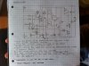
I have recently bread boarded this filter schematic that I had made from adapting one of R.A Penfolds circuits (see pic attached), unfortunately I couldn't seem to get it working, after speaking with a technician at uni and analyzing the output with an oscilloscope I was told that the bias created from the 3k9 resistor that links pin 3 of the LM13700N to the positive rail wasn't high enough. Also the range of the cut-off seemed to be quite small and when the LFO was sidechained the signal would begin to clip. Finally the output of the circuit was very inconsistent. I' m not really sure if there is any easy way round these problems, any suggestions would be appreciated.

Thanks
 

Attachments

  • adapted filter schematic.JPG
    adapted filter schematic.JPG
    483.3 KB · Views: 217
It's not clear what all this circuit is supposed to do. Can you elaborate?
 
For me, it looks like the opamp symbol is drawed wrong. On top/bottom shall biasing and supply voltage terminals be, and on the left side (on your opamp symbols) shall the inbverting and noninverting inputs be. Otherwise it's very confusing to read.
 
What is the amplitude of the input signal? Why do you have some positive feedback around the first amp i.e. 27k & 47k pot, is that some kind of Q adjustment? Do you really need the variable gm of the LM3700, they are complicated compared to ordinary op amps. The bias looks OK as long as the input signal stays within bounds(+1.5 to +7.5). I've only looked briefly at the first stage.
 
Hi, thanks for all the responses, the circuit is meant to be a filter, the switch between pins 8 and 9 and the output is to toggle between lowpass and bandpass, and the 47k pot is meant to control the Q factor aka resonance. Finally the switch between the 100k pot and the jack socket is to toggle between manual control of the cut off and use of an external LFO that I ve built. Sorry the schematic isn't very clear I was in a bit of a hurry, hopefully this clarifies. I m pretty sure there is problem with the bias as the circuit seems to respond better when when the 3k9 resistor is replaced with with variable one so that the bias can be adjusted accordingly, maybe a diode would do the trick?
 
Your suspicion looks correct as the min cmr is within 3v of either supply. Bias the input to half the supply i.e. make both resistors the same. The supply is a possible problem, as the minimum supply used in the applications is +/-5v, but if it works, it works. Your diagram was fine, and complete.
 
Status
Not open for further replies.

Latest threads

New Articles From Microcontroller Tips

Back
Top