Continue to Site

Welcome to our site!

Electro Tech is an online community (with over 170,000 members) who enjoy talking about and building electronic circuits, projects and gadgets. To participate you need to register. Registration is free. Click here to register now.

  • Welcome to our site! Electro Tech is an online community (with over 170,000 members) who enjoy talking about and building electronic circuits, projects and gadgets. To participate you need to register. Registration is free. Click here to register now.

Low voltage logic trigger

Status
Not open for further replies.

BruceS57

New Member
I found a couple of related posts about this, but nothing that showed exactly what I am looking for, so...

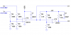
I need a simple (defiinately, because I'm a hobbiest/newbie) circuit that triggers a logic switch if a sensed input voltage falls below a varying reference voltage. It would work like this:

r = reference voltage
s = sensed voltage
v = +5 (logic high)
o1 = output 1
o2 = output 2

if s < r then v is connected to o1
if s >= r then v is connected to o2

Both r & v can vary from 0 to +80 VDC. Note that the circuit will not be passing any real current, just sensing the potential present on r and s and making either o1 or o2 high.

Thanks (again)! You folks have been great and a real help.

Bruce
 
Why 80V?

That's far higher than any comparator I know of will work, you could use potential dividers I suppose but why make life harder for yourself?
 
Questions about answers...

philba said:
use voltage dividers to bring R and S (should be Vr and Vs) down to 5V or so...

Philba,

Thanks for responding!

Please bear with me on this...:confused:

By "divider", do you mean something like a resistor to step down the voltage?

Also, in looking at the spec sheet, it appears that the greater voltage from
-Input1 and +Input1 is passed to Output1. If that's the case, let's assume the two following situations:
Vr = 1.5 and Vs = 1
Vr = 50 and Vs = 24

If one uses the same "divider" to step down the 50V to 5V (divide by 10) as is used to step down the 1.5V, the 50V Output is fine but the 0.15V volt Output is too low to trigger a logical True. How can this be handled with the Comparator shown?

Preference is to output fixed 5V supplied from Vcc, not sourced from either
-Input1 or +Input1.

hero999 said:

The typical range is 0-60VDC, with 48VDC most common. Went to 80 because I'd rather overbuild than to have the circuit fail and shut down the entire device.

Thanks, again, guys.
 
What are the desired states of o1 and o2 when they are not high? Do you want them to float (no connection), to be connected to 0 volts, or ???.
If you use resistive dividers, this means that Vr and Vs must source current. Do you know the source resistances of Vr and Vs, or, do you know how much current they can source?
 
Last edited:
"Off" states and available currents

Steve,

Need logical low (0V) for False. Vr current is minimal - actually comes from regulated power supply or batteries. Its only function is to provide the reference voltage. Vs available current can be high - up to 100 amps at 48VDC.

Thanks,
Bruce
 
Do you have another supply available for the comparator? An LM339 (or LM393) can handle up to 36 volts, which means your Vs and Vr attenuation would not have to be too great. The output is open collector, so you can still output a 5 volt logic signal.

PS don't call me Steve. :D
 
wikipedia on voltage divider: https://en.wikipedia.org/wiki/Voltage_divider

If you divide both Vr and Vs by the same amount, you will be fine. I'm not sure, though, why do you need to divide your reference? just create it for the divided value of Vs you want to switch at. I'd run the comparator at 12V unless you are using standard logic or microprocessors and then I'd use 5V.

Hmmm, Vs 48V at 100A. You need to explain this one a little better. How are you sensing it? What generates it? I'd bet it's not the cleanest power around so you will all sorts of nasty effects.

my name's not steve, either.... :)
 
Sorry about that, Chief...

Ron,

Sorry for the name slip! That's what I get for being in a hurry. While I was responding, my wife was waiting on me to leave to go see some friends. (Guess what his name is!)

Unfortunately, limiting to 36VDC is not an option.

I really appreciate you taking your time on this. As you can tell, I'm out of my primary field (automation programming) but have a problem I need to solve for a customer. I checked all of my normal suppliers for a networked module that would do voltage thresholds, but none of them had one. The intent is for this circuit to feed to a logic module, which is available. My software can then test that module and change processing accordingly.

By allowing Vr to vary, I was trying to make the circuit more flexible so that it can be used in multiple applications. Could go with a fixed reference voltage (Vr) for each different application or use an on-board pot to set it.

For this first one, I need to set the trigger level at 48VDC. If Vs is that much or more, I need one output high and the other low. If less, they should be reversed. (The second output allows me to more easily chain the circuits, but I could live with only one output of High if Vs < 48, Low if >=48.)

Do you know of something that will work?

Best,
Bruce
 
I wasn't suggesting that you switch 36 volts. Re-read my previous post. If you don't understand the concept of open collector, see the Wikipedia description, or Google it.
The circuit below draws 2.5mA max (0.8mA typ) from the +30V supply (which could be as high as 36). I was assuming that, if you could provide a high voltage reference, you could also provide a supply for the comparator.
If you can come up with this supply, this circuit could of course be modified to better suit your needs.
 

Attachments

  • HVcomparator.PNG
    HVcomparator.PNG
    16.4 KB · Views: 132
Ron,
Wouldn't it be a good idea to add some hysteresis?

Connect a 1M resistor from the output of U1b to its + input.
 
There's also no reason to use 80V and an attenuator to feed the other comparator input, you simply need a potentiometer across the 30V supply rail, which would give him his required adjustment.
 
Nigel Goodwin said:
There's also no reason to use 80V and an attenuator to feed the other comparator input, you simply need a potentiometer across the 30V supply rail, which would give him his required adjustment.
True. I was just addressing his original request, where the reference is on the same scale as the signal. No calculations required this way, but I agree it's somewhat of a Rube Goldberg solution to the problem.
Hero, hysteresis is good, if he can tolerate it. It might be essential. However, a 1Meg from the output would seriously shift the reference.
 
Last edited:
I know it would shift the voltage but isn't a 100mV or so of shift worth making it more stable?
 
Hero999 said:
I know it would shift the voltage but isn't a 100mV or so of shift worth making it more stable?
I agree with you. I just don't think it's as simple as adding a 1 Meg feedback resistor. With the circuit I posted (which,as Nigel suggested, may not be ideal, and which I said could be modified to better suit his needs), the apparent hysteresis (referred to the reference) would be about a volt, and the apparent shift in a 60 volt reference would be more than 3 volts. Ten Megs would be a better choice, and might be acceptable.
 
Status
Not open for further replies.

Latest threads

New Articles From Microcontroller Tips

Back
Top