Continue to Site

Welcome to our site!

Electro Tech is an online community (with over 170,000 members) who enjoy talking about and building electronic circuits, projects and gadgets. To participate you need to register. Registration is free. Click here to register now.

  • Welcome to our site! Electro Tech is an online community (with over 170,000 members) who enjoy talking about and building electronic circuits, projects and gadgets. To participate you need to register. Registration is free. Click here to register now.

Low voltage alarm - 12f629

Status
Not open for further replies.

samtheboxer

New Member
Hello, I need some help! :D

I am new to PIC's and so far have been programming different flash patterns using PicBasic pro and the 12f629. I have a little electronics experience (simple circuits) and very little programing experience.

I would like to program a chip to flash an LED pattern and when my LIPO battery drops to about 9.5 volts, i would like the LED pattern to change.

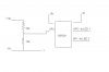
I have a schematic for a voltage alarm using a maxim 8211 chip. I was thinking about using that to trigger the change in patterns on the PIC, but if its at all possible, i would like to just use a single chip in the circuit, so have the whole deal programmed into the chip (it doesnt have to be a 12f629, that is just what i am using now)

Im am a little frustrated by the material i have come across so far, its more complex than i need (i dont want to program robots or computer interfaces!) so......

can anyone point me in the right direction or recommend some good resources for pic basic and the type of programing i would like to do?

or, maybe you could help me with the program and help me figure out the circuit...

thanks for all your help.
 
Get a low voltage signal from the MAX IC and feed it into the GP3 in the 12F629.

Show your patterns as they were and write a GP3 INPUT DETECT routine inside your DELAY1 routine (DELAY1 = delay used in the first pattern). If detected GP3 has a signal then shift to the other pattern.

So other pattern delay will be DELAY2 again detect GP3 inside this DELAY2 repeat this …….continue……
 
The 629 has a comparator. You could use this with a voltage divider to detect when the voltage has dropped below 9.5V. This would only take up 1 I/O pin (GP1) if you use the internal voltage reference. Have a read of the data sheet.

Mike.
 
Gayan Soyza said:
Get a low voltage signal from the MAX IC and feed it into the GP3 in the 12F629.

Show your patterns as they were and write a GP3 INPUT DETECT routine inside your DELAY1 routine (DELAY1 = delay used in the first pattern). If detected GP3 has a signal then shift to the other pattern.

So other pattern delay will be DELAY2 again detect GP3 inside this DELAY2 repeat this …….continue……

So by delay you mean my flash pattern loop? so, if it looks like this

Loop
High 1
pause 500

low 1
pause 500

goto loop

end

cant i insert an IF statement saying that if pin X were high or if an input was detected, then goto loop2?

The 629 has a comparator. You could use this with a voltage divider to detect when the voltage has dropped below 9.5V. This would only take up 1 I/O pin (GP1) if you use the internal voltage reference. Have a read of the data sheet.

Mike.

So i read through the data sheet and understood maybe 10% of it!! :confused:

Basically, from what i understand, i can run a 12v current from the battery then split it in two, one half running through a regulator bringing it down to 5v to feed the chip and the other half running to the chips input (after running it through a series of resistors to bring it down in voltage). the 5v to the chip with stay constant and create an internal voltage reference to compare to the current coming from the battery. as the current drops, the chip with detect the change and "interrupt" the program when it hits a set voltage difference?

am i close?
 
samtheboxer said:
So by delay you mean my flash pattern loop?

I mean like this but this is an example.

Code:
PAT1	movlw	b'00000001'
	movwf	PORTB
	call	DELAY1
	movlw	b'00000010'
	movwf	PORTB
	call	DELAY1
	----
	----
	goto	PAT1

PAT2	movlw	b'00000001'
	movwf	PORTB
	call	DELAY2
	movlw	b'00000010'
	movwf	PORTB
	call	DELAY2
	----
	----
	goto	PAT2


DELAY1	btfss	GP3	;check the GP3 button is it pressed or not
	goto	Del_1	;NO its not pressed then carry on actual delay
	goto	PAT2	;YES its pressed then goto PAT2

Del_1	decfsz	d1,f	;actual delay (scaning speed)
	goto	$-1
	decfsz	d2,f
	goto	$-3
	return

DELAY2	------
	------
 
samtheboxer said:
So i read through the data sheet and understood maybe 10% of it!! :confused:

Basically, from what i understand, i can run a 12v current from the battery then split it in two, one half running through a regulator bringing it down to 5v to feed the chip and the other half running to the chips input (after running it through a series of resistors to bring it down in voltage). the 5v to the chip with stay constant and create an internal voltage reference to compare to the current coming from the battery. as the current drops, the chip with detect the change and "interrupt" the program when it hits a set voltage difference?

am i close?

You got it.

With something like a 10K resistor from your supply to GP1 and a 5K from GP1 to ground, you would set CMCON=4 (b'00000100'), VRCON to 176 (b'10101111') and bit 6 of CMCON will be set when your voltage is below (approx) 9.5V. No need for interrupts. FYI, I've roughly calculated this so it may be wrong!!

If you swap the resistors for a preset potentiometer then you can set the voltage exactly.

Mike.
 
Pommie said:
You got it.

With something like a 10K resistor from your supply to GP1 and a 5K from GP1 to ground, you would set CMCON=4 (b'00000100'), VRCON to 176 (b'10101111') and bit 6 of CMCON will be set when your voltage is below (approx) 9.5V. No need for interrupts. FYI, I've roughly calculated this so it may be wrong!!

If you swap the resistors for a preset potentiometer then you can set the voltage exactly.

Mike.

so, my cicruit would look something like this (sorry, i used these values before i saw your post)

the voltage at 12v at GP3 would be 3.75v and the low or trigger voltage would be 3v. Does this look right? Also, where does that ground from the divider go?
 

Attachments

  • VD.JPG
    VD.JPG
    14.9 KB · Views: 430
You should only have 1 ground which connects to,
The negative terminal of your battery,
The gnd connection on your 5V regulator,
The Vss pin on the pic.

I'm assuming that the -5V refers to the gnd connection of the regulator and the -11 (why not -12) refers to the -ve battery terminal. I'm also assuming you have some capacitors around your regulator.

Mike.
Edit, the input should go to GP1 if you only want to use 1 pin.
 
Pommie said:
You should only have 1 ground which connects to,
The negative terminal of your battery,
The gnd connection on your 5V regulator,
The Vss pin on the pic.

I'm assuming that the -5V refers to the gnd connection of the regulator and the -11 (why not -12) refers to the -ve battery terminal. I'm also assuming you have some capacitors around your regulator.

Mike.
Edit, the input should go to GP1 if you only want to use 1 pin.

yeah, the -11 should be -12, sorry, im at work and flipping back and forth trying to use MSPaint!

So, to run it off a 11.1v (usually 12V) LIPO, can i use the +5 volts from the regulator (yes, there is a proper power supply, i just didnt draw it) and then run the -12v to the regulator and the chip (its okay that is a 12V ground?)....

Thanks, I will draw up a proper schematic after work. Thanks for your help, I want to get the circuit right and then build on that...
 
Status
Not open for further replies.

Latest threads

New Articles From Microcontroller Tips

Back
Top