Continue to Site

Welcome to our site!

Electro Tech is an online community (with over 170,000 members) who enjoy talking about and building electronic circuits, projects and gadgets. To participate you need to register. Registration is free. Click here to register now.

  • Welcome to our site! Electro Tech is an online community (with over 170,000 members) who enjoy talking about and building electronic circuits, projects and gadgets. To participate you need to register. Registration is free. Click here to register now.

Low power output from fets, can anyone help?

Status
Not open for further replies.

Swifty

New Member
Hi all,

I have been working on a small circuit the last few days which is designed to be an RGB Led Controller.
I am no electronics expert and have been learning as I go, but I've hit a problem with my finished board and can't figure out what is happening..
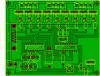
The circuit was built using the diagram attached, and everything is indentical except I had to use IRFZ44N fets as I could not source IRFZ14 locally..

Now to the problem.. all the leds on the board work (they are just there for testing so you don't have to attach anything to the outputs) but I get very low voltages from the actual outputs - all of them are giving around 0.02v - 0.08v, it should be more like 12v!
I have metered the voltage at the gate of the fet and they are all around 2.02v

Have I done something wrong or has the change of components screwed something up ?

Thanks!
 

Attachments

  • momolight_crontrol.gif
    momolight_crontrol.gif
    41.4 KB · Views: 375
We need your schematic. Your gate voltage is way too low to turn on the IRFZ44. John
 
Hi John,

Thanks for your reply.
Is that referred to as the 'gate threshold voltage' ?

Hi Neil,

No. Gate threshold is where the gate starts to turn on, and can explain why your output is so low. You need to fully turn on the gate to have it act like a switch. For the Mosfet you are using, that is approximately 10V.

I attached the schematic I used to make the circuit in the original post;
https://www.electro-tech-online.com/attachments/momolight_crontrol-gif.21930/
Is it something different you need ?

Yes. What you posted was the PCB layout. The schematic shows symbols, part numbers and values, and connections.

John
 
No. Gate threshold is where the gate starts to turn on, and can explain why your output is so low. You need to fully turn on the gate to have it act like a switch. For the Mosfet you are using, that is approximately 10V.

Ah ok, thanks John - I presume the voltage for turning the IRFZ14 fully on is lower than the IRFZ44 ?
I spoke to the person who drew that PCB layout yesterday and they mentioned I should never see higher than 5v at the gate as its fed 5v from the PIC..
If that is the case then will I have to replace the IRFZ44's with 14's ? Or is there anything I can modify to make it work?

Yes. What you posted was the PCB layout. The schematic shows symbols, part numbers and values, and connections.
Apologies.. it's my first time doing anything this ambitious so some of the terminoligy can get confusing :p
I don't think there is a schematic with symbols etc.. available for the exact layout I used, its design originates from here if its any help?; **broken link removed** but that design is missing the fets.

Thanks
Neil
 
Ah ok, thanks John - I presume the voltage for turning the IRFZ14 fully on is lower than the IRFZ44 ?

No, it isn't. If you look at the datasheet, you will notice the threshold voltages are the same, and RDS(on) is given at 10V gate.

Are you sure it was not an IRLZxx? The "L" is low voltage and will turn on at 5V.

John
 
Hi Swifty,

The leds are connected accross the gate-source junction of
the mosfets. This will prevent the fets to be driven. You
should at least get 4 to 5 volt drive to get anything out
of the fets. Check the Vgs/Id characteristic in the datasheet.
You need to remove the leds to get the thing working!

The output voltages will always be zero because the drains are
connected to the outputs, this means that you need to connect
the external leds with the anodes to the + 5 volts (com ?)
and the cathodes go to the drains of the fets. And don't forget
to put a resistor in series with the leds to limit the current,
otherwise the fets will fry the leds.

Have much fun !

on1aag.
 
Thanks to both for your help.

John, the info for making the board definatley states IRFZ not IRLZ..

on1aag, thanks for your input - I _think_ I now understand what you are saying; If I look at the datasheet for the fets it says the threshold is 2 > 4v so above 4v the fet will begin to output ?
And the fets are only getting around 2v because ~ 2-3v are being sucked by the leds which are inline with the supply to the fets?

Hopefully I have understood that correctly :)

Thanks!
 
Ok in answer to my own question I guess I understood things correctly!

I have just desoldered the +ve leg from one of the LEDs on the board and I now see 12v at the output for that channel!
Thank you so much o1aag!
 
Hi Swifty,

With only 5 volt drive these fets can sink up to 500 mA,
so don't push it. If you want more you'll need to replace
them with logic level fets and . . . those are expensive.
You can get some for free if you've got old motherboards.

on1aag.
 
The gate threshold voltage is 2V to 4V. The drain current at the threshold voltage is only 0.25mA which is barely turned on.

If you find a Mosfet with a 2V threshold voltage then it will conduct many Amps with a 5V gate to source voltage.
If you find a Mosfet with a 4V threshold voltage then it won't conduct much current with a 5V gate to source voltage.
The Mosfets are guaranteed to conduct many Amps with a 10V gate voltage.
 
Status
Not open for further replies.

Latest threads

Back
Top