Continue to Site

Welcome to our site!

Electro Tech is an online community (with over 170,000 members) who enjoy talking about and building electronic circuits, projects and gadgets. To participate you need to register. Registration is free. Click here to register now.

  • Welcome to our site! Electro Tech is an online community (with over 170,000 members) who enjoy talking about and building electronic circuits, projects and gadgets. To participate you need to register. Registration is free. Click here to register now.

Low power LED flasher with one shot latch . Help required

Status
Not open for further replies.

phil_s

New Member
Hi all I have been asked to make something to the following criteria

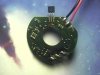
A flashing LED in an environmentally sealed enclosure, visible in total darkness at 200M with a lifetime of 12 months minimum.

All of the electronics and the battery also need to be inside the sealed enclosure, in fact it will probably be potted. There are to be no external switches.


For LED visibility I think I will be using an 8mm LED the problem is how I activate and deactivate it.

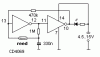
I have thought of using a reed switch and activating it by a magnet, the problem is I need to have some type of latch that maintains power as when I remove the magnet the reed switch will open. I then need to disconnect power by operating the same reed switch again but I'm not sure if this is possible.

Any suggestions on the switching circuit and suggestions of the best way to have a bright LED with low current consumption for extended battery life will be appreciated. I am planning to use a PP3 9V battery.

Many Thanks

Phil
 
Use a bipolar Hall-switch. It swich on with magnet North-pole and off with South-pole. Canibalize it from a bearing-failed DC brushless motor (PC-supply).
 
Sebi said:
Use a bipolar Hall-switch. It swich on with magnet North-pole and off with South-pole. Canibalize it from a bearing-failed DC brushless motor (PC-supply).
Really!?!?
where would this part be located..
i just happen to have one..
would that be it at the top??
 

Attachments

  • hall_sensor.jpg
    hall_sensor.jpg
    16.7 KB · Views: 864
i just tested it ..
Yes that is the hall effect switch..
it pays to not throw stuff out.. :lol:
 
Problem is I need to make a few hundred of these and I don't think I would find that many supplies to rip apart :)
The hall swiches are quite expensive to buy and I'm woorking on a very tight budget

Any other suggestions will be much appreciated
 
phil_s said:
Problem is I need to make a few hundred of these and I don't think I would find that many supplies to rip apart :)
The hall swiches are quite expensive to buy and I'm woorking on a very tight budget

Any other suggestions will be much appreciated

How about a reed relay with an external magnet?.
 
Since this is pretty low power, how about 2 reed switches.. one to fire a small SCR, and start the thing running, the other to short it out and turn it off?
 
That could be a good solution, I was actually thinking about doing it with two reed switces an sr latch and an analogue switch but maybe my theory is maybe a bit complex.
Would you happen to have a diagram of how to do it with the SCR and when on is the quiescent current drain of the scr as low as using discrete CMOS IC's

Many Thanks

Phil
 
The Infineon hall-switch cost only a half euro, in my country equal to small reed-tube. Also try Allegro Microsystems.
 

Attachments

  • hall.gif
    hall.gif
    37.4 KB · Views: 788
The discussion inspired me to look at my old high-voltage detector probe. It looks like a flashlight with a big point and a corona guard. It uses a slide switch like a flashlight to turn it off and on. Figuring it must be isolated from the possible contact of 50,000 volts the tip could touch, I wanted to see how it switched it on.

Guess what. Sebi has the answer. The switch knob/slider contains a small bar magnet. Inside the device ( on the other side of the plastic case ) is a hall detector. In one position, the sliding magnet has one pole over the detector, the other position the other pole.

The circuit is potted on the PCB surface, with only the detector exposed, but from what I can see this is exactly what they are doing.
 
I think the problem with the Hall effect switch solution although a very convenient one is that firstly they are not so readily available at a low price here in the UK, and secondly as I work with Hall Effect (not switches) I know that you usually need to drive the hall device weith a few mA before you get a decent output which will be detremental to the battery life.

Regards

Phil
 
Right. Power consumption is a neuralgic point.
Here is a simple CMOS flip-flop with reed contact.
 

Attachments

  • on_off_184.gif
    on_off_184.gif
    2.2 KB · Views: 713
white LED cluster , would like to make it flash - constantly on.

Hi i have White LED cluster and would like it to flash and also remain constantly on. Just as you may have seen on a bike light.

The only problem is i am using a 3.7v 650ma mobile phone battery, and would like the circuit diagram for the above mentioned.

The LED cluster is drawing 400ma. Please could anyone help me with the circuit diagram. I am trying to get high brightness out of the LED,s so the circuit must have at least 400ma output.

Can anyone help?

Thank you

fc
White cluster on a tail light? you should be using a single lighting class red LED.
 
Status
Not open for further replies.

Latest threads

New Articles From Microcontroller Tips

Back
Top