Electro Tech is an online community (with over 170,000 members) who enjoy talking about and building electronic circuits, projects and gadgets. To participate you need to register. Registration is free. Click here to register now.
Welcome to our site! Electro Tech is an online community (with over 170,000 members) who enjoy talking about and building electronic circuits, projects and gadgets. To participate you need to register. Registration is free. Click here to register now.
"When I have no suitable inductancemeter available, I use the resonance method, based on the Thomson formula: https://en.wikipedia.org/wiki/Resonant_circuit
You need a good reference capacitor, say 100nF 0.5% or 1%, polystyrene or polypropylene, you make a tank circuit with the unknown coil and you feed the circuit via a resistor of some Kohm.
You connect a scope across the circuit and you sweep your generator until you find a signal peak; you then calculate the inductance using the reverse Thomson formula: 1/C*(6.28*F)².
With 100nF and 1µH, the frequency is around 500KHz.
The signal generator has to be preferably sinusoidal, otherwise you will get parasitic peaks at harmonic frequencies. Even if it is the case you can still get the correct value by selecting the highest and strongest peak.
The method is very accurate and only depends on the accuracy of the reference cap. In addition you can select a cap value giving a resonance frequency near the intended operating frequency of the inductance, giving an even better accuracy."
unclejed613 also has some good ideas for a series resonant circuit that would be more accurate...
**broken link removed**
**broken link removed** http://electronics-diy.com/
I have a $6000.00 meter and a $50.00 meter like the links above. The $50 meter is real good. It does a good in the 0.1uH-10uH range. Simple to use.
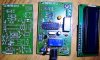
i have a pcb for AADE type LC meter adopting !6F628A, with software by Phil Rice of Australia.
It is later published in siliconchip and EPE magazines.
I have changed the mechanical switch with another relay to help reduce the wires from and to the board. This is more useful for radio hobby as the Inductance minimum is 1nH and cap min is 0.1pF
max inductance would be 1mH or so.
I have modified the artwork to miniaturize and also added a relay replacing the L_C changeover switch.
**broken link removed**
**broken link removed** http://electronics-diy.com/
I have a $6000.00 meter and a $50.00 meter like the links above. The $50 meter is real good. It does a good in the 0.1uH-10uH range. Simple to use.
This site uses cookies to help personalise content, tailor your experience and to keep you logged in if you register.
By continuing to use this site, you are consenting to our use of cookies.