Continue to Site

Welcome to our site!

Electro Tech is an online community (with over 170,000 members) who enjoy talking about and building electronic circuits, projects and gadgets. To participate you need to register. Registration is free. Click here to register now.

  • Welcome to our site! Electro Tech is an online community (with over 170,000 members) who enjoy talking about and building electronic circuits, projects and gadgets. To participate you need to register. Registration is free. Click here to register now.

Low frequency oscillator circuit

Status
Not open for further replies.

vielle568

Member
Hi Everyone,

I'm building a musical instrument and I need a series of 12 oscillators to create the base for a chromatic octave. I've tried using a 50240 chip and it works OK (using a crystal oscillator as the clock) but the IC is something from the 70's and draws a lot of current and it's far too much for my battery powered project.

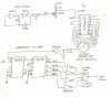
I've been trying to use a simple circuit based on a 7414 inverting buffer IC (schematic below). There's just a capacitor and a resistor controlling the frequency and I can get the range I want (200 to 500Hz), but the circuit isn't completely stable and tends to waver and drift over time.

Does anyone have any suggestion for either: 1) a low power, low frequency oscillator that is stable and will not drift, or 2) a method (or an IC) for dividing a frequency into the twelve tones required for an octave?
Thanks for any suggestions,

Vielle568
 

Attachments

  • 555-to-Schmitt-Osc-3.gif
    555-to-Schmitt-Osc-3.gif
    4.7 KB · Views: 798
Last edited:
What are the exact frequencies you need for the base octave?
 
Hi Mike,
The frequencies required form a chromatic octave running up from middle C:

C 261.6Hz
C# 277.2Hz
D 293.7Hz
Eb 311.1Hz
E 329.7Hz
F 349.2Hz
F# 370.0Hz
G 392.0Hz
G# 415.3Hz
A 440.0Hz
Bb 466.2Hz
B 493.9Hz

Asssuming that the signal generated by the oscillator is a square wave the frequency can then be divided by 2, 4, 8 and 16 using a 7493 IC to obtain lower octaves. It worked alright like this using the 50240 chip but it took far too much power.
The idea of using a synthesizer module does not seem practical because it requires a keyboard (or a keyboard buss) to create the control voltage required for the VCO. Any ideas?
vielle568
 
Last edited:
Hi Mike,
The frequencies required form a chromatic octave running up from middle C:

C 261.6Hz
C# 277.2Hz
D 293.7Hz
Eb 311.1Hz
E 329.7Hz
F 349.2Hz
F# 370.0Hz
G 392.0Hz
G# 415.3Hz
A 440.0Hz
Bb 466.2Hz
B 493.9Hz

Asssuming that the signal generated by the oscillator is a square wave the frequency can then be divided by 2, 4, 8 and 16 using a 7493 IC to obtain lower octaves. It worked alright like this using the 50240 chip but it took far too much power.
The idea of using a synthesizer module does not seem practical because it requires a keyboard (or a keyboard buss) to create the control voltage required for the VCO. Any ideas?
vielle568

hi,
The 50420 only draws about 25mA.??

Have you seen this link: electro-music.com :: Index - electro-music.com
 

Attachments

  • datasheet.pdf
    296.8 KB · Views: 311
Last edited:
Last edited:
Hi,
I'm not looking for something as sophisticated as a synthisizer. All I need is a device to generate a stable frequency at a the musical intervals. I am developing the yellow instrument in the photo. It is an electric/electronic version of the hurdy-gurdy. The melody comes from the keyboard via steel strings and a magnetic coil pick-up similal to an electric guitar. However the instrument also has a rhythm that can be generated by acceleration of the crank and a drone accompanyment that's normally provided by additional strings. My prototype uses a laser system to sense the wheel speed to trigger an analog switch for the rhythm effect; the drone strings will be replaced by an oscillator.
I've used the circuit in the attached diagram but it seems to draw too much current. I assumed that the old S50240 chip was the culprit but I could be mistaken as it draws 25mA (unloaded). If anyone can point out what's causing the load I'd be most grateful. Thanks
 

Attachments

  • CCT.JPG
    CCT.JPG
    313.3 KB · Views: 925
Last edited:
What supply voltage is the 74HC14 powered with? 5V?

How are you making the 5V out of 12V?

Reasons the circuit is likely pulling too much current:
The 2.2K pullup on the CLK input is much too low. When the FET is on, I= 12/2.2K = 6mA. Try 20K, or even higher.
Likewise, the voltage divider after the rotary switch. Try 50K series, 33K shunt.
Get rid of the TTL counters and replace them with HC equivalents.
 
Last edited:
this sounds interesting !
several questions = what controls the 4 pos switch? Then what controls the 12 pos switch?
your description sounds very appetizing, like I need to build same. Your description is kinda vague but then I need to do a search of a Hurdy-Gurdy.
Last time I ever heard of a Hurdy-Gurdy was I think it was Donanvan in Hurdy-Gurdy Man.
 
Hi,
I'm not looking for something as sophisticated as a synthisizer. All I need is a device to generate a stable frequency at a the musical intervals. I am developing the yellow instrument in the photo. It is an electric/electronic version of the hurdy-gurdy. The melody comes from the keyboard via steel strings and a magnetic coil pick-up similal to an electric guitar. However the instrument also has a rhythm that can be generated by acceleration of the crank and a drone accompanyment that's normally provided by additional strings. My prototype uses a laser system to sense the wheel speed to trigger an analog switch for the rhythm effect; the drone strings will be replaced by an oscillator.
I've used the circuit in the attached diagram but it seems to draw too much current. I assumed that the old S50240 chip was the culprit but I could be mistaken as it draws 25mA (unloaded). If anyone can point out what's causing the load I'd be most grateful. Thanks

hi,
Have you considered a total 12V powered circuit.?
Use a HEF4049B as the main oscillator to drive the MK50240 and a HEF4520B as the dividers.
 
The 74HC14 runs off 5 volts that comes from a 78L05 regulator that's driven by a block of 8 'AA' batteries. This is how I have been getting my 12 and 5 volt sources for the circuit. The schematic shows only part of the overall system; the frequency generator for the drone. To answer Eric's question the two rotary switches are are set manually by the player to chose a drone to accompany the music; one switch selects the tone and the other selects the required octave.

I'll try making the changes you've suggested Mike; the circuit is simle enough and it works OK but it's taking a little too much power. I'll get back to you when I have some more info. Thanks for the suggestions.

For MrDEBB, if you're interested in taking a look at hurdy-gurdies then take a peek at the link below. These are some of the modern electro-acoustic instruments that are now being made by instrument makers. So far no one has yet come up with a solid-body electric version and modified the instrument in the same manner as the guitar was transformed into an 'electric' instrument back in the 1950's. This is what I am hoping to do, but I have still a way to go...

Site Luthier : contemporary creations hurdy gurdy, buy sell hurdy gurdy

No, I haven't considered a totally 12v system because there's a lot more you haven't seen and most of it runs on 5 volts.

vielle568
 
Last edited:
If you're only using one tone at a time, you could consider a programmable divider. The MK50240 appears to contain a bunch of dividers, one for each tone.
 
Thanks for your suggestion mneary, that's exactly what I'm aiming for and in fact what I started off doing. If you take a look at the schematic tied to an earlier link in this discussion you'll see the 50240 in the circuit being used to generate the required tones. My design seemed to draw too much power for the batteries but I've since had some suggestions on how to correct that problem so I'm in the midst of changing some components and trying again. Hopefully it'll be more efficient this time.
Vielle568
 
Status
Not open for further replies.

New Articles From Microcontroller Tips

Back
Top