Continue to Site

Welcome to our site!

Electro Tech is an online community (with over 170,000 members) who enjoy talking about and building electronic circuits, projects and gadgets. To participate you need to register. Registration is free. Click here to register now.

  • Welcome to our site! Electro Tech is an online community (with over 170,000 members) who enjoy talking about and building electronic circuits, projects and gadgets. To participate you need to register. Registration is free. Click here to register now.

Low Battery Indicator w/ 6V supply

Status
Not open for further replies.

tbr75

New Member
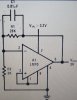
I'm trying to get a battery indicator on a GPS project that I'm making. I've attached a circuit that I found that works for a 9V supply. I will be using a 6V supply. What do I need to change to make it work for my supply? The zener diode?

The supply consists of 4 new 1.5V AAA alkaline batteries.
 

Attachments

  • BattCheck.gif
    BattCheck.gif
    7.7 KB · Views: 1,148
If you change the zener to about 3.9 V it should work. Be aware that the circuit will take about 10 mA and will kill AAA alkalines in about 100 hours by itself.

You should either fit a pushbutton switch to turn on the battery indicator, or replace the green LED and the 330 R resistor with a 10 k resistor. That will drop the current to very little until the voltage is very low and the red LED comes on.
 
Low voltage zener diodes still conduct at a voltage much lower than their rating.
Four alkaline battery cells are 6.4V when new and drop to 4.0V during their life. The circuit needs a reference voltage much less than 3.9V.

An LM10 is an adjustable voltage reference plus an opamp in an 8-pins case and is perfect for this job.
 
If you change the zener to about 3.9 V it should work. Be aware that the circuit will take about 10 mA and will kill AAA alkalines in about 100 hours by itself.

You should either fit a pushbutton switch to turn on the battery indicator, or replace the green LED and the 330 R resistor with a 10 k resistor. That will drop the current to very little until the voltage is very low and the red LED comes on.

I am going to change the 330R resistors to 1K to help limit the current. This isn't required for the project, it's actually part of my "novel features". I want the green light so that it will show when the batteries are charged so that the professor can see that it works. Otherwise he'd have to replace the batteries with dead batteries to see if the red light comes on. However, I may implement the push button idea. Thanks.

Low voltage zener diodes still conduct at a voltage much lower than their rating.
Four alkaline battery cells are 6.4V when new and drop to 4.0V during their life. The circuit needs a reference voltage much less than 3.9V.

An LM10 is an adjustable voltage reference plus an opamp in an 8-pins case and is perfect for this job.

If I were to use a LM10, would I use it with the circuit I've attached? Also, where could I find this op amp? They did not have one in our stockroom and I didn't see it on Radioshack's site.
 

Attachments

  • 100_2205.jpg
    100_2205.jpg
    1.1 MB · Views: 358
Radioshack sells cheap kids toys and cell phones, not electronic parts.
Digikey has more than 6,000 LM10 ICs in stock today and billions of other electronic parts.
The datasheet shows how to use it.
 
This is my first 'real' project, all my other projects I was given all the parts I needed. So thanks for the link to Digikey, it will be useful.
 
Status
Not open for further replies.

Latest threads

New Articles From Microcontroller Tips

Back
Top