Continue to Site

Welcome to our site!

Electro Tech is an online community (with over 170,000 members) who enjoy talking about and building electronic circuits, projects and gadgets. To participate you need to register. Registration is free. Click here to register now.

  • Welcome to our site! Electro Tech is an online community (with over 170,000 members) who enjoy talking about and building electronic circuits, projects and gadgets. To participate you need to register. Registration is free. Click here to register now.

Love Birds Picture on Wedding Frame Project

Status
Not open for further replies.

phil1017

New Member
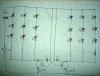
hello. im still a beginner. im gonna put alot of leds on love birds picture. two bird wings should be flipping out and in. im still figuring how to flash the leds by the wings. i have to test it on the breadboard to see if its working or not.

2 5mm leds
two transistors (BC547B)
two 22µf capacitors
470Ω for leds
100kΩ for capacitors
9V battery

it seem two leds are not flashing, the one led is still light on and the second led is fading out and dimmed. i think its probably the transistors which can't turn switchs. i have seen many schematics where the transistors is inserted exactly but its not. what is your suggestion/ideas? thanks!

(if you want to see the picture of breadboard, then lemme know)
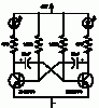
 
For now, we'd much rather see the schematic rather than the breadboard. Something is probably wrong with the way the flashing mechanism is wired up in the schematic or the design. But schematic is easiest to start with to try and figure out how you are trying to go about things.
 
Last edited:
ok here is the schematic...
 

Attachments

  • DSC01852.JPG
    DSC01852.JPG
    1.4 MB · Views: 201
Which two LEDs did you build? One per side so far?

Also, in the schematic you have 3 LEDs per branch sharing a single current limiting resistor. It's better to have one resistor per LED because in real life the voltage drop across LEDs is not the same and the accumulated might cause one LED to be pushed over it's current limit. The more conservative (larger) your resistor value is though the less of a problem this will be but the more dim they will run as well.

I must admit I'm having trouble trouble mapping out what's going in the circuit particularilty with the capacitors.
 
Last edited:
yes one per side but i didn't build two leds. wanna make sure if the transistors is insert properly. some icons on the schematic made me confused like where is E, B and C is. that's why im used two leds to see if its flashing or not. i found few problems with it.

i have tried to test 3 leds on per side. its the same thing again. all leds are fading out and dimmed and no flashing. i believe it can be the resistors, transistors and/or capacitors.
 
I'm still having trouble thinking about how the capacitor is charging and discharging current paths which is key to how the flashing is supposed to happen. There's a lot going on in that little circuit.

Question: Since you didn't build it with the LED chain, did you use the same resistor values? Or did you modify them to account for the fewer LEDs? With fewer LEDs the resistor has to be higher. YOu must have though, or else the LEDs would be very bright just before burning out (assuming the circuit is actually doing what it's supposed to be doing), which you say they aren't.
 
Last edited:
Where did you get this circuit from? I can sort of see how the circuit is trying to work, but I keep running into little hiccups here and there in it's operation. Maybe someone else will have better luck because these kinds of circuits are not my strength.

EDIT:
Attached is a similar looking circuit I found (but not the same). I've spent some time trying to figure out how this circuit works and it makes a lot more sense to me than the one you provided.
https://wild-bohemian.com/electronics/flasher.html
 

Attachments

  • t-flash2.gif
    t-flash2.gif
    3.4 KB · Views: 170
Last edited:
I just realized they're the same circuit. The smaller one was just easier to take in. Hmmm.
 
i used the same resistor valves like 470Ω for two leds and 1kΩ for three leds per sides. its the same thing. you think that capacitors 22µf is too much absorbing the power? think 10µf is good?

i made the two flashing kits and studied the schematics. i tried to design my own schematic similar to other schematic. but its not working. i guess im unlucky. i have been working hard to get the right way for two weeks.
 
Status
Not open for further replies.

Latest threads

New Articles From Microcontroller Tips

Back
Top