Continue to Site

Welcome to our site!

Electro Tech is an online community (with over 170,000 members) who enjoy talking about and building electronic circuits, projects and gadgets. To participate you need to register. Registration is free. Click here to register now.

  • Welcome to our site! Electro Tech is an online community (with over 170,000 members) who enjoy talking about and building electronic circuits, projects and gadgets. To participate you need to register. Registration is free. Click here to register now.

Looking for a 4 bit prescaler good to 500 MHz

Status
Not open for further replies.

BobW

Active Member
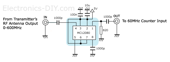
I'm looking at building a PIC based frequency counter. I'll be using one of the 16F series PICs which have integrated timer/counters that are good to 50 MHz. I'd like to add an external 4-bit prescaler so that I can increase the upper frequency limit to 500 MHz. I've done a bit of checking around for suitable prescalers, but there seems to be a big gap in frequencies. 74AC logic seems to top out around 150 MHz, and then there's a jump into the GHz range when going to ECL prescalers (eg. MC12080, MC12093 etc.). Is anyone aware of anything that's good up to 500 MHz, preferably with normal logic level outputs?
 
There is a gap from 290mhz and 650mhz. So if you want 500mhz there is no TTL.
You probably can't find a fast 1/10.
1/2, 1/4, 1/8

The parts you picked are probably best.
 
What parts are good to 290 MHz? I may revise my specs downwards.
 
A lot of the pre-scalers have been discontinued for whatever reason. At some point in the future, I might want to build a /256 up to 1 GHz to incorporate into an existing instrument that had one as an option, but I'm not up to it nor has the need arisen.
 
'ACT16x are rated for 125MHz at 5V and if you overclock at 5.5V or 5.8V with cooling maybe 200 from the fastest supplier. CMOS runs faster when colder than room temp.

I think Current Mode Logic (CML) is your best bet, if you can interface to it. (LVDS 100Ω)
https://www.ti.com/lit/ds/symlink/cdcl1810.pdf 650MHz divide ratios of 1, 2, 4, 5, 8, 10, 16, 20,
32, 40, and 80

1.8V CML to CMOS is easy.
 
Interesting. I checked the Fairchild website, and found the same low frequency ratings that Tony Stewart mentions.
https://www.fairchildsemi.com/datasheets/74/74VHC161.pdf
So, there seems to be a significant difference between manufacturers.
I did a bit more research and found that the highest speed CMOS currently available seems to be the 74VHC family, and I found the 74VHC4040 has a typical maximum clock speed of 210 MHz (Fairchild), which would probably keep me happy. I did find the 74ACT175 quad D flip flop has a max clock frequency of 244MHz (Fairchild again), but by tying the /Q output back to the D input to get a ripple counter, the propagation delay would likely drop the max frequency to less than the 74VHC4040.

I think Current Mode Logic (CML) is your best bet, if you can interface to it. (LVDS 100Ω)
https://www.ti.com/lit/ds/symlink/cdcl1810.pdf 650MHz divide ratios of 1, 2, 4, 5, 8, 10, 16, 20,
32, 40, and 80
1.8V CML to CMOS is easy.
Thanks.
Hmm, not sure I want to deal with a 48 pin package and the other complexities. Gives me a bit more to think about though.
 
I remember back when Fairchild were fastest and MOT the slowest and NSC inbetween. Looks like TI is faster now.

Remember to use microstrip impedances and try to terminate with something like pull/up+down or whatever to balance around threshold if going for max.
 
Thanks. It looks like the MC12080 is still the cheapest option though.

BTW, Does anyone notice anything strange about the frequency counter schematic on the Electronics-DIY page that Ron posted?
https://electronics-diy.com/50MHz_Frequency_Meter_Counter.php
The incoming signal is fed into the Timer 0 input, and they specify 60MHz max frequency with a resolution of 10Hz. That means that they must be using the prescaler, but there's no way to read the prescaler directly in the processor. So, an external connection is needed to flush the prescaler contents. I wonder if they deliberately did not show the connection in order to keep the method a "secret". If so, it's rather amusing, because it's a well known method for reading the prescaler, traceable back to an ancient Microchip frequency counter appnote. Yet, it seems that with almost every frequency counter project I've seen, the designers either try to obscure how they do it, or else they try to let on that they invented the method.
 
The design appears to use 4MHz Xtal to measure inputs up to 60MHz on PIC counters and then show the /10 prescaler to extend the f range to 600 MHz and /20 to measure frequencies up to 1.2GHz.
MC12080-prescaler.jpg

The only oddity to me is the display of 1 Hz resolution on the display but a spec of 10 Hz resolution.

A 10 Hz resolution using a 4MHz ref clock on 50Mhz requires a count of 5x10e5 or a 19 bit counter. Is that right?


60MHz_Frequency_Meter_Counter_PIC16F628A.jpg
 
My last post may have been a bit confusing, because I was referring to the internal prescaler in the PIC processor, not the 1 GHz external prescaler that we had been discussing earlier.

I suspect the resolution changes over the complete frequency range. It may be 1 Hz at the lowest frequencies, and then decreasing at higher frequencies. Most of the PIC frequency counters that I've seen are based on this app note:
https://ww1.microchip.com/downloads/en/AppNotes/00592d.pdf
It's a design for an auto-ranging frequency counter with a total range from 50 Hz to 50 MHz, and the resolution changes over that range. The point that I was making about reading the prescaler is discussed on the first page of the app note. Timer/counter 0 is only an 8 bit counter, with an optional 8 bit prescaler which cannot be read within the processor.
 
The 8 bits in the prescaler are “shifted out” by toggling RA2 with a “BSF” and a “BCF” instruction
 
Status
Not open for further replies.

New Articles From Microcontroller Tips

Back
Top