Continue to Site

Welcome to our site!

Electro Tech is an online community (with over 170,000 members) who enjoy talking about and building electronic circuits, projects and gadgets. To participate you need to register. Registration is free. Click here to register now.

  • Welcome to our site! Electro Tech is an online community (with over 170,000 members) who enjoy talking about and building electronic circuits, projects and gadgets. To participate you need to register. Registration is free. Click here to register now.

logic tester

Status
Not open for further replies.

Melfior_Ra

New Member
Hi all.

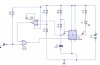
I am trying to build a logic tester. Nothing special. There are tons of diagrams ver the internet but i chose to create one by myself.

The problem is : When "1" or pulse is applied on the input the circuit acts as expected. But when "0" is applied the output of 555 is switching high and low. Now in this case i cant see the difference beetween 0 logic and pulse. What is wrong?

Thank you in advance.
 

Attachments

  • tester.JPG
    tester.JPG
    41.6 KB · Views: 183
hi,
Basically its because the trigger pin #2, is being held Low, this will disable the operation of the 555 circuit.
 
Yes. But on 0 logic at the entrace of the OR gate the 555 is not disabled, the output is switching between high and low even with high on pin 2 of the 555. Maybe i am missing somethig please explain to me. I am noob and i am trying to learn.
 
Pardon me if I'm missing something obvious here, but it looks as if your tester simply lights the LED on a logic high, but does nothing on a logic low.

Wouldn't you want two lights, one for high and the other for low?

(Or does your circuit blink the LED in one state and turn it on steadily in the other?)
 
Last edited:
This is only a part of the full circuit. This part is used to monitor pulses. If i have a 1khz at the entrance of the OR gate the led will flash with the frequency of the 555. When the capacitor is low (the voltage on non inverting pin of the 339 is lower than 840 mV) on the exit of 339 i will have 0 and it will trigger again.
 
Basically its because the trigger pin #2, is being held Low
I don't see how.
If the OR gate lower input is held at 0V, C1 can still charge up. As soon as its voltage reaches > 840mV the LM339A output will go high, as will the OR gate upper input, and hence trigger pin 2 of the 555 goes high. The 555 will then operate in astable mode (oscillate), with C1 repeatedly charging via R6,R8 and discharging via R6 and resulting in the hi/lo switching the OP is experiencing. In this mode the C1 voltage is always > 840mV, so pin 2 is locked high.
 
But with High on trigger (pin 2 of 555) the output of 555 will stay forever low. Why is oscillating?
 
Last edited:
But with High on trigger (pin 2 of 555) the output of 555 will stay forever low. Why is oscillating?

hi,
You say its only a part of the circuit, so post the full circuit so that we can give the correct advice, rather than trying to guess.
 
But with High on trigger (pin 2 of 555) the output of 555 will stay forever low.
One of us has misunderstood the operation of a 555 (it could well be me!). AFAIK when pin 2 is high the 555 is 'triggered', and can act as a monostable or astable pulse generator (depending how it's configured). When pin 2 is held low the 555 is disabled and its output stays high.
We need a referee! Any volunteers?

Alec,
With a high on the Trig pin2 it will run as an astable, when held low it will be disabled.
 
Thanks Eric.
So there you are, Melfior_Ra. Your 555 is running as an astable, as I suggested in post #6.
HTH
hi,

removed edit!
 
Last edited by a moderator:
I'm not sure precisely what the OP expects from this circuit, but would replacing the OR gate by an AND gate achieve the desired result?
 
I'm not sure precisely what the OP expects from this circuit, but would replacing the OR gate by an AND gate achieve the desired result?

alec,
In LTS, AND gate is the same result.
 
To run as an astable pin #2 must be linked to pin #6.
Pin 2 is linked to pin 6 .....via IC2 and IC1. So the conditions are met for astable operation.
I agree it would help if we knew the intended function of the circuit.
 
@Eric
How did you manage to add your Edit to my post #11? Admin rights?
 
hi.
In LTspice, when trig #2 is held low, output #3, is high.

When trig #2 is held high , output #3 is low.

To run as an astable pin #2 must be linked to pin #6.

If the OP told us what he wanted to happen when input is Low and High, it would help.
 
I am a bit confused. I am using circuit wizard to simulate and isis. Now in theory the monostabile mode is something like this:

Initial condition. Trigger HIGH => Output LOW
Trigger LOW => Output high for amount of time = ~1.1xRC after this period of time Output goes LOW.
Now in both software with Trigger High Output is High..... !!!!!!!!!!!!!!!!!!!!!!!!!


Please correct me if i am wrong.

@ericgibbs: This part of the circuit is only for pulses is separate from the rest it will be activated by a switch Thats why i said the rest circuit it is not important.
I think I can figure what happend : With Low on first entrance of OR gate and Low on Non inverting input of 339 (LOW on second entrance of OR gate) trigger is low => output is high. Now you cant stop the HIGH cycle (you can only by putting reset to ground). After capacitor discharge 339 will see again low on pin 6 and the cycle begins again. My problem is why I have a LOW period at the output?

PS. Please excuse my english.
 
Last edited:
hi Melfior,
For a monostable , the Trig pin2 is pulled to 0V for a short pulse, then it must be allowed to remain high until the next low trigger pulse.
 
Why use a 555. Go the KISS method, use two transistors, couple of resistors. Have seen numerious such circuits on the web.
 
Status
Not open for further replies.

New Articles From Microcontroller Tips

Back
Top