Continue to Site

Welcome to our site!

Electro Tech is an online community (with over 170,000 members) who enjoy talking about and building electronic circuits, projects and gadgets. To participate you need to register. Registration is free. Click here to register now.

  • Welcome to our site! Electro Tech is an online community (with over 170,000 members) who enjoy talking about and building electronic circuits, projects and gadgets. To participate you need to register. Registration is free. Click here to register now.

Logic Question

Status
Not open for further replies.

MrMikey83

New Member
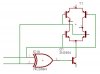
I have an H-Bridge chip and I need to be able to make sure I dont have both inputs on at the same time or it will cause a short from +V to Gnd. So, I have two inputs from the ATmega and two outputs to the H-Bridge. I need a circuit that will allow each input to control its corrosponding output but I need all outputs off if both inputs are on.
~Mike
 
What H-bridge IC are you using?
Are you sure it will short out, maybe it has built in protection for this by tri-stating the output.
 
I have some ZGB6790 chips I am planning to use. They can handle 40Volt supply at 2Amps.
Heres the datasheet:
http://www.zetex.com/3.0/pdf/ZHB6790.pdf#search='Bipolar%20transistor%20H%20Bridge'

Inside the package are 4 transistors set up like a very simple H-Bridge, there is no built in protection. If you were to turn on B1 and B2 for example, it would short out wouldn't it?

Also, will B1-B4 trigger off of 5 volts?
~Mike
 
MrMikey83 said:
I have some ZGB6790 chips I am planning to use. They can handle 40Volt supply at 2Amps.
Heres the datasheet:
http://www.zetex.com/3.0/pdf/ZHB6790.pdf#search='Bipolar%20transistor%20H%20Bridge'

Inside the package are 4 transistors set up like a very simple H-Bridge, there is no built in protection. If you were to turn on B1 and B2 for example, it would short out wouldn't it?

Also, will B1-B4 trigger off of 5 volts?
~Mike

Yes they will short out like you suspsect. This package is just 4 transistors so, you'll have to do all the fun work of making it run without killing itself.

Just bipolars, yes - they'll run off of 5 volts.

While each transistor has those kind of specs, you probably wont be able to run them at those levels continuously. Pretty small package, you should definately watch your power dissipation.
 
A cheap CPLD might be the easiest solution. You can get a 36 macrocell Xilinx CPLD for ~$3.50. The design software is free.

You could generate all the delays in software but that might be a bit risky.

You could also use a couple NAND gates to prevent shoot-through. A RC circuit on one NAND input with the other input connected directly to the signal will generate a delay pulse.
 
Its will be a PWM signal into the H Bridge for motor speed control, so hopefully heat wont be a huge issue with the pulsed operation. I'll take a look at other H-Bridge circuits and try to get some ideas from them of how exactly to connect the NAND gates.
~Mike
 
Also...Do I need to add flyback diodes to each transistor or is the voltage low enough that it shouldn't be a problem?
 
Beacuse the motor can be run both ways you can't really have a flyback diode. You can use a low ESR capacitor instead that will help to kill the voltage spikes.
 
There are capacitors (small ceramic) already soldered onto the motor for noise control. WOuld those filter out the spikes as well?
~Mike
 
Those will probably be fine. They probably were added for just that reason - big voltage spikes create lots of noise.
 
Would this circuit work?
 

Attachments

  • h.jpg
    h.jpg
    37.4 KB · Views: 1,185
Feel free to draw the fix on the above picture. I was mostly worried about if the XOR gate would work or not. The H Bridge needs to turn off if I accidentally put a high on both forward and backward pins (short).
 
So will the XOR logic work?
 
OK then...

I am trying the circuit below (except Q1 and Q4 are PNP's) and I am only getting .05 volts to the motor terminals. I don't have the LED's in there but that shouldn't matter. I tried both 12V and 5V to the base's of the transistors and still only .05 volts to motor terms. Is there a better circuit that I can use?
~Mike
 
OK, I figured out the H-Bridge and it works perfectly. Back to my original question...how to provide protection from accidentally turning on both inputs and creating a short. I tried using an XOR gate connected to a transistor but that didn't work (I didn't expect it to). I know I can use the XOR gate, but I'm not sure how to use the output to turn off the circuit. I could use a small relay to cut off power.
~Mike
 
I think you're thinking about it the wrong way. The logic should turn on the H-bridge transistors themsleves (with some driver circuitry if nessesary). For the top transistors you want a PWM input and a control input - if the control input is high you let the PWM through if its low you turn the transistor off.

Top Transistor 1 => (Direction AND PWM) : if Direction is high PWM goes through.

Top transistor 2 => ((NOT Direction) and PWM) : since you use the inverse of direction you can not have the PWM going to both top transistors.

You Turn the bottom transistors on all the time with the direction bit and the inverse of the direction bit. You insert a small turn on delay when the direction bit changes to prevent shoot-through as all the transitors turn off.
 
OK, I was trying to have an input for forward and an input for backward and put PWM through to both inputs. I guess I should try having PWM on one input and forward/reverse on the other input. WIll probably solve a lot of problems.

Bigger problem now though...
Earlier today, after I got the H-Bridge working, I decided to connect a motor to it and see if it ran the motor at 12 volts. It moved very slowly and then smoked my h-bridge chip. OK, so I decide to see how many amps it really uses at full speed. I got out the power supply I made my freshman year in college and put it at 12 volts and connected my multimeter in series to measure amps. I turn it on and pop, I blow out the 12 volt regulator in my power supply. Great! Is there a way to figure out the amperage of this motor without actually testing it by running it?
~Mike
 
Measure the resistance of a DC motor and Ohm's Law will tell you the maximum current it will draw when fully loaded. Its maximum current probably won't occur at full speed unless it is heavily loaded or its bearings bind. Maximum current will occur at start-up, when its inertia is a very heavy load, and when it is stalled.
Of course its current is multiplied if it is running in one direction and you reverse its supply to run it in the other direction. It is best to stop it by shorting it, then reverse it.
 
Alright, I set my meter to resistance and connected to the motor. Reading .1 Ohm on the motor rated at 14 Volts, I get 70 Amps. Does this sould right?
If I rotate the motor, I get 1kOhm and 14mA
~Mike
 
Status
Not open for further replies.

Latest threads

New Articles From Microcontroller Tips

Back
Top