Continue to Site

Welcome to our site!

Electro Tech is an online community (with over 170,000 members) who enjoy talking about and building electronic circuits, projects and gadgets. To participate you need to register. Registration is free. Click here to register now.

  • Welcome to our site! Electro Tech is an online community (with over 170,000 members) who enjoy talking about and building electronic circuits, projects and gadgets. To participate you need to register. Registration is free. Click here to register now.

logic gate

Status
Not open for further replies.
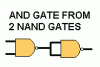
hi can ne one tell me the way to make an AND gate from a set of NAND gates and doe sne one have a Nand gate chip design?

if someone knows can they plz write it like this

_
_D- for and

_
_Do- for Nand

thanks!
 
WHAT IS WRONG WITH A PICTURE?
 

Attachments

  • and_from_nand.gif
    and_from_nand.gif
    1.7 KB · Views: 480
  • and_gates.gif
    and_gates.gif
    11.1 KB · Views: 458
evandude said:
what do you mean chip design? that's sort of vague.

erm like this

...........___
pin 1-|.....|- pin 8
pin 2-|.....|- pin 9
pin 3-|.....|- pin 10
pin 4-|.....|- pin 11
pin 5-|.....|- pin 12
pin 6-|.....|- pin 13
pin 7-|.....|- pin 14
............----.
_
and the _Do- on the inside, u used to have one but i lost it
 
that's going to depend on what chip you use... why don't you go download the datasheet for the chip you want to use?

for example the 7400

https://www.electro-tech-online.com/custompdfs/2004/09/SN7400_74LS00_74S00.pdf

there isn't a picture with the gates drawn into the chip but on the first page there is the chip labeled with all the info you need: for instance, 1A and 1B are the inputs to the first NAND gate, and 1Y is the output. 2A,2B are the inputs for gate 2, and 2Y is the output, etc. for all 4 gates in the chip. If you really want a pictorial diagram then you can very easily draw one from that datasheet.
 
How's This?

---____ ____
---I----U-----I
[1]-----------[8]
---I---555---I
[2]--Timer---[7]
---I----IC----I
[3]------------[6]
---I-----------I
[4]------------[5]
---I_______I
 
hotwaterwizard said:
WHAT IS WRONG WITH A PICTURE?

picture is fine, it's the content 8)

one problem is that AND gate is just a basic element of digital electronics. the whole idea of digital circuits is that you could have tons of basic gates connected into one large circuit.

the diode version of the AND circuit for example can work if the inputs are connected to low impedance outptus. problem is that this cannot be done with the diode AND circuit you posted. (well you can connect it but it won't work).
 
Status
Not open for further replies.

Latest threads

New Articles From Microcontroller Tips

Back
Top