Electro Tech is an online community (with over 170,000 members) who enjoy talking about and building electronic circuits, projects and gadgets. To participate you need to register. Registration is free. Click here to register now.
Welcome to our site! Electro Tech is an online community (with over 170,000 members) who enjoy talking about and building electronic circuits, projects and gadgets. To participate you need to register. Registration is free. Click here to register now.
I need to create a simple logic gate setup where I have 8 inputs.
The circuit needs to output 1 if more than one input is high.
Otherwise (if 1 input is high, or if no inputs are high) it needs to output 0
You'll probably just need a two bit counter and use bit 1 OR 2 as your output. Trying to do it with combinational logic won't be easy. Or use a 256 bit look up table.
If you can use an analog approach then just sum all the inputs through equal value resistors (one resistor for each input) into a comparator. Select the comparator threshold to about 3/16 of the logic high voltage such that more than one high input triggers the comparator.
can be implemented using 4017 with sequential logic as shown.. the high frequency clock will be refreshing the key status, making the 2nd 4017 to set and reset the out put.
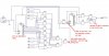
I read your question backwards, then put together a schematic. After reading it again and adding a not gate to the output I believe this circuit is all you need. Although a little robust it could be simplified by programming in assembly or using a karnoff map. I believe there a simplified way to karnoff map with a larger number of inputs.
I read your question backwards, then put together a schematic. After reading it again and adding a not gate to the output I believe this circuit is all you need. Although a little robust it could be simplified by programming in assembly or using a karnoff map. I believe there a simplified way to karnoff map with a larger number of inputs.
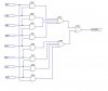
Another brute force approach: The are nine conditions to check for the logic input not being true -- all 0's on the input or only one input being 1. This can be done with nine 8-input NOR gates.
For the 8-input NOR gates connect each gate to the 8 logic inputs as follows.
1st gate-- All logic inputs connected directly to the respective gate inputs (all 0 check)
2nd gate --Logic inverter connected to first input, all other inputs connected directly
3rd gate -- Logic inverter connected to second input, all other inputs connected directly
4th gate -- Etc.
The outputs of these nine NOR gates go to a 9-input NOR gate (the Output).
The nine 8-input NOR gates thus determine if all inputs are 0, or if any single input is 1. Those are the conditions for an output 0 (2 or more logic inputs high criteria not met).
Thus if any of the eight gate outputs are 1 then the output NOR gate is 0.
If all of the eight gate outputs are 0 then the 2 or more high criteria is met and the output NOR gate output is 1.
Assuming the receiver (after this circuit) has predefined HI and LO thresholds (especially if those thresholds are close together) it can probably be done with a resistor divider (or a pot) and 8 resistors to the 8 inputs.
That would be a no-gate solution.
Another solution would be a NPN transistor and 8 resistors to it's base and a base resistor to ground. It's collector would pull low when 2 or more inputs are high. It's a very low parts count solution but the output is inverted to what the OP asked for.
Another brute force approach: The are nine conditions to check for the logic input not being true -- all 0's on the input or only one input being 1. This can be done with nine 8-input NOR gates.
For the 8-input NOR gates connect each gate to the 8 logic inputs as follows.
1st gate-- All logic inputs connected directly to the respective gate inputs (all 0 check)
2nd gate --Logic inverter connected to first input, all other inputs connected directly
3rd gate -- Logic inverter connected to second input, all other inputs connected directly
4th gate -- Etc.
The outputs of these nine NOR gates go to a 9-input NOR gate (the Output).
The nine 8-input NOR gates thus determine if all inputs are 0, or if any single input is 1. Those are the conditions for an output 0 (2 or more logic inputs high criteria not met).
Thus if any of the eight gate outputs are 1 then the output NOR gate is 0.
If all of the eight gate outputs are 0 then the 2 or more high criteria is met and the output NOR gate output is 1.
More interesting than as I originally read it... If only gates allowed (no micro);
1 answer: takes qty 9, 8 input OR gates along with qty 8, 2 input AND gates.
If this is a homework assignment, the instructor may realize you didn't think of this... Bad Dog, No Biscuit! (teehee) <<<)))
Thanks for the replies.
This is not a homework assignment, just a circuit I'm trying to prototype.
Realizing the number of gates / cost and quantity of components I think it would be easier to do w/ a micro.
Hey, at least it provided a bit of a design challenge for the gurus on the forum
This site uses cookies to help personalise content, tailor your experience and to keep you logged in if you register.
By continuing to use this site, you are consenting to our use of cookies.