Continue to Site

Welcome to our site!

Electro Tech is an online community (with over 170,000 members) who enjoy talking about and building electronic circuits, projects and gadgets. To participate you need to register. Registration is free. Click here to register now.

  • Welcome to our site! Electro Tech is an online community (with over 170,000 members) who enjoy talking about and building electronic circuits, projects and gadgets. To participate you need to register. Registration is free. Click here to register now.

Logic design help needed

Status
Not open for further replies.

Sonia123

New Member
Hey folks,

First, I am new to this forum and am glad such communities exist.. Cheers to the Managers in here!!
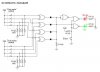
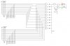
Second, I have a problem with my very first digital project which is a combination lock. It will have ten possible combinations and I want to make use of red and green LEDs for correct and incorrect results or probably some sort of an alarm for wrong combination. I have attached a schematic for four combinations and I would really appreciate your wonderful effort if you could give some ideas for extending the circuit up till ten combinations since I am brand new to this field.
Here's what I think, I think that there would be ten XOR gates instead of four along with the data entry switches. What do you think?
Thanks alot
 

Attachments

  • Combination Lock.JPG
    Combination Lock.JPG
    36.3 KB · Views: 158
It already has 16 differant posible combinations. Look here;**broken link removed**
 
If you have to use small scale (gates) then you can use the attached schematic,just extending the EXOR gates and the diodes which acts as OR gates.

You may use bit comparator chips like 4585 to simplify wiring,each chip is a four bit comparator so you will use three chips to compare ten bits (extra two bits are not used).
 

Attachments

  • Combination Lock10.JPG
    Combination Lock10.JPG
    85.9 KB · Views: 191
Thank you so much buick51! You're the best :)
But I want to know one thing, I am going to use XOR gates as bit comparators. Wouldn't I have to replace the gate with the comparator if I use the ones you suggested?
 
Yes ,chip will replace EXOR gates.
One chip will replace four EXOR gates and actually it will replace the entire (4 input) circuit as this chip has an output pin that goes high if the four input bits are equal to the four preset (or what you call key code) bits,so three chips can make 10 bits circuit.
 
That would be perfect for avoiding the mess but what about the other two bits, wouldn't they be used since this way, there would be eight switches but I need to have ten of them. What do you think about it?
 
Three chips would make 3*4bits =12 bit comparator ,we only need 10 bits so the extra 2 bits are not used we may connect them to ground.

There is a schematic (motorola datasheet for this chip mc14585) that shows how to cascade three chips to have 12 bit comparator without using extra components ,use only 10 bits and connect the extra 2 bits to ground(both sides data input and preset or key code).
 

Attachments

  • bit comp.GIF
    bit comp.GIF
    4.7 KB · Views: 122
Oh yes yes. That would be so cool. By the way, I just curious to know, are you using Eagle for the schematics you just posted?
Thanks a lot
 
Status
Not open for further replies.

Latest threads

Back
Top