I couldn't find anything concerning my case, so I write it here...
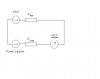
I'm working with photon multiplier (Hamamatsu R928) - detecting a light signal over the scanning sample. Because the signal is really low I want to add lock-in amplifier (Standford Research Systems SR830). Unfortunately the signal from PMT is about 3V (constant value) modulated with changes of light intensity due to changes in scanning sample's surface. The problem is that lock-in amplifier's input is only +-1V. I tried to get rid of that "background" voltage by using scheme below, but it didn't work (and also don't know why).
Moreover I came accross the next problem, while I was trying on simpler light and PMT output was within a range. When I connected PMT to lock-in amplifier (input parameters 10MOhm/25pF) it had problems with detecting signal and phase lock it. But if I connected PMT through simple amplifier (Philips 1MOhm/20pF; output: 50 Ohm) with amplification 0dB the signal was OK. So, in principle, it works but I have to use amplifier, which does nothing. It's stupid. Can someone explain me the reason for that?
Thank You in advance,
Chris.