Continue to Site

Welcome to our site!

Electro Tech is an online community (with over 170,000 members) who enjoy talking about and building electronic circuits, projects and gadgets. To participate you need to register. Registration is free. Click here to register now.

  • Welcome to our site! Electro Tech is an online community (with over 170,000 members) who enjoy talking about and building electronic circuits, projects and gadgets. To participate you need to register. Registration is free. Click here to register now.

LM723 Basic high voltage regulator

Status
Not open for further replies.

Bluehotel

New Member
Hello guys,

I'm currently trying to build a basic high voltage regulator thanks to a LM723.
I have a 220V sine voltage which I reduce to 25V thanks to a transformer and that I transform into a DC voltage with a diode bridge and a capacitor.
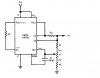
Then I'd like to regulate this voltage thanks to the LM723 between 10 and 20V under a max current of 100mA. I'm using a the basic high voltage regulator circuit that I found in the datasheet (figure 2 : output between 7 and 37V) :https://www.electro-tech-online.com/custompdfs/2010/03/LM723PDF.pdf
I set Rsc at 10ohm so that I get a max current of 65mA.

Nevertheless, I didn't manage to configurate the resistors and the potentiometer so that I get a regulated voltage between 10 and 20V (Actually, I can't get how to set them to set the upper and lower voltage limits) . The max voltage that I get is about 13.5V when I simulate it on Pspice Orcad.

Where does my mistake lie ? (I'll post my circuit in Pspice as well)

Thanks a lot for your help.
Regards.
 
Why not use an LM317?

Surely that's the easiest method.

Or do you want to set the current limit?

A separate current limiting circuit can be made with a couple of transistors, although it won't be as good as the LM723, it is simpler.
 
Refer to the circuit in the attachment.

For a variable output with definable upper and lower limits, you will need to have a potential divider with three resistors R1 R2 and RV.

RV being the pot used to adjust the output voltage.

The reference voltage of a 723 is 7.15 volts. (It does have a tolerance, see the datasheet).

When the 723 is operating normally and correctly as per the circuit, the voltage at the INV pin will be 7.15 volts.
When we adjust the pot (RV) to the R1 end to get 10 volts output, Vlow will be 7.15 volts. (Vout divided down by R1, RV+R2).
When we adjust the pot (RV) to the R2 end to get 20 volts output, Vhigh will be 7.15 volts. (Vout divided down by R1+RV, R2).

From this we can make a couple of equations.
R2 = ((Vlow/Vhigh) x RV)/(1 - (Vlow/Vhigh))
R1 = ((Vhigh x R2) - (7.15 x (RV + R2)))/7.15

Now:
Select a value for RV, I suggest 1k ohm.
Calculate the value of R2
Calculate the value of R1
Build and test the circuit.

Simple!

JimB
 

Attachments

  • 723 Regulator..JPG
    723 Regulator..JPG
    51.1 KB · Views: 4,827
Thanks for your answers Hero999 and JimB.
Actually, i'm not allowed to use a LM317 which would have been simple, that's right. I also can't use transistors.
I'll try the equations you gave me, JimB. I had already done the circuit you attached but first without the potentiometer to make it more simple.

I'll keep you informed and add you my simulations on Pspice.
Have a nice day !
 
I stand corrected, it seems like the LM723 is easier to use than an LM317 plus a couple of transistors for current limiting. I'm not familiar with the LM723, even though it's a fairly common part.
 
The LM723 is years old, I first came across them in the mid 1970s.

I am sure there must be better devices around now.

I would not call the 723 "easy to use", but it is versatile.

I have just "built" a bench power supply using a 723.
The PSU output is variable from about 2 volts to 30 volts in two ranges.
The maximum safely usable current is about 0.5 to 1 amp depending on the voltage, one day I may sort out the current limiting which at the moment is up around 4 amps.

The PSU is actually a modification of a commercial "component power supply", the sort of thing you can buy off the shelf to incorporate into your own equipment.
Mine was built by a company called PowerOne, they make lots of these things.
The one I have has been in my "junk box" for many years, having been salvaged from somewhere too long ago to remember.
In its original form it was rated for 24volts 4.5amps.

JimB
 
Last edited:
The LM723 is years old, I first came across them in the mid 1970s.

I am sure there must be better devices around now.

I don't think so, it just seems to keep going on and on (like a Duracell Bunny :D) - I've never seen anything to repace it.

But as you say, it's decades old now.
 
I have just "built" a bench power supply using a 723.
The PSU output is variable from about 2 volts to 30 volts in two ranges.
The maximum safely usable current is about 0.5 to 1 amp depending on the voltage, one day I may sort out the current limiting which at the moment is up around 4 amps.
You say there are two ranges?

Are you using a centre tapped transformer?

Are you switching to the centre tap for the lower voltage range?
 
Last edited:
Hero,

Nothing as sophisticated as that, all I have done is select the feedback potential divider ratio to give adjustable ranges of 1 to 10 volts and 3 to 30 volts.

There are of course problems with such a simplistic approach, notably high power dissipation in the pass transistors when supplying high currents at low output voltages.
Not the best solution, but I decided that it was valid for my own application since I understand the limitations.

JimB
 
Hello,

I calculated the values of R1 and R2 and found 797.2 and 1kohm (potentiometer = 1kohm). So I'll take 820ohm for the value of R1.
For the current limit, I'll choose Rsc=6.8ohm wich gives me a Iout of 0.09 A (90mA).
Then I'll connect these components so as to build a high voltage comparator circuit.

Am I right, so far ?
Thank you.
 
Hello,

I calculated the values of R1 and R2 and found 797.2 and 1kohm (potentiometer = 1kohm). So I'll take 820ohm for the value of R1.
Am I right, so far ?
They look like the values I calculated.
If you use 820 ohms for R2, the output will not quite reach 20volts.
You may want to put another resistor in parallel with the 820 ohm to give something nearer to 797 ohm.

JimB
 
Good evening,

Here is the circuit I built on Pspice : R1=797ohm, R2=1kohm, RV potentiometer set to 1kohm in this case and R3=R1//R2, Rsc=6ohm for current limiting.

My voltage source is an AC source with Vampl=25V which should be enough to reach a Vout of 20V (markers V+ and V-).
With these settings, I should get an exact Vout of 20V.

Nevertheless, my Vout is never higher than 13.5V (even if I have a 35V source or different resistors values).

Does the problem come from Pspice or is my circuit wrong ?

I observe that if I set the settings well to get a Vout of 10V, I get it.

**broken link removed**

**broken link removed**

Thanks for your help.
 
Last edited:
...my Vout is never higher than 13.5V (even if I have a 35V source or different resistors values).

Does the problem come from Pspice
Who knows? Never mind playing computer games, get the soldering iron out and burn your fingers on real components.;)

or is my circuit wrong ?
Yes it is, have a good look at the circuits in the datasheet and then remove the connection from pin 9 (Vz).
A real one will then work correctly, not sure what the computer game will do.

JimB
 
Why do you have two of the terminals on the bridge rectifier connected to ground?

And why all those pop-ups?
 
Why do you have two of the terminals on the bridge rectifier connected to ground?
A very good point, I did not look at his rectifier!
Another good reason for not using computer games, smoke is a good teacher!

JimB
 
Who knows? Never mind playing computer games, get the soldering iron out and burn your fingers on real components.;)


Yes it is, have a good look at the circuits in the datasheet and then remove the connection from pin 9 (Vz).
A real one will then work correctly, not sure what the computer game will do.

JimB

You are right. I modified a few things in the part properties to let the Vz connection float so I don't get an error.
Now, it's working properly and I get a voltage between 10V and 20V depending on the setting of the potentiometer.


Why do you have two of the terminals on the bridge rectifier connected to ground?

And why all those pop-ups?

Yes, it's pretty strange, but I have to do it, or else, it 'won't work. Or I have to add a load resistor...
 
Status
Not open for further replies.

New Articles From Microcontroller Tips

Back
Top