Continue to Site

Welcome to our site!

Electro Tech is an online community (with over 170,000 members) who enjoy talking about and building electronic circuits, projects and gadgets. To participate you need to register. Registration is free. Click here to register now.

  • Welcome to our site! Electro Tech is an online community (with over 170,000 members) who enjoy talking about and building electronic circuits, projects and gadgets. To participate you need to register. Registration is free. Click here to register now.

LM567 help need

Status
Not open for further replies.

aruna1

Member
Hi
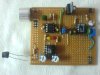
I'm working on a tone decoder for my ultrasonic receiver. my goal is to detect input signal and verify whether its 40kHz. I'm using LM567chip for this. circuit is tuned for 40kHz and measured at pin 5.

my problem is circuit isn't working as it should be (according to data sheet)


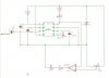
please note in following diagrams C4 should be 0.02uF. I have incorrectly marked it as 0.001uF.


First attempt
This is the first circuit I tried

**broken link removed**

In this circuit LED does not light for the 40khz input signal. actually LED wont turn on what ever input it get.

Second attempt

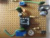
Then my second attempt is disconnecting capacitor C1 from pin 1. then LED turned on dimly when there is no input and LED lights brightly when detecting 40kHz signal. this is the circuit

**broken link removed**


Third attempt

in my third attempt I connected 100k resistor from 5V to pin 1. after that LED is turned off when there is no 40khz input and LED turns on when detecting 40khz signal. but problem is now circuit responds to sounds other than 40khz signal.sounds like clapping and tapping sounds. when clapping LED blinks faintly.
here is the circuit
**broken link removed**

Forth attempt

here I connected both C1 and R3 as in data sheet but result is same as attempt 1. LED doesn't turn on with or without signal
this is the circuit
**broken link removed**


This is kind a funny. I cant figure out what the heck is wrong. first I thought LM567 was burned so I brought another but results are same.

can someone help me here? I'm pretty frustrated. ??? :p
thank you
 
hi,
Look at this image, your C! 0f 0.02uF gives a freq of ~4.5KHz with a 10K.
Try a 0.002uF cap.
 

Attachments

  • AAesp01.gif
    AAesp01.gif
    31.5 KB · Views: 878
Hi
I used a 10k potentiometer and adjusted it to give 40khz with 0.02uf capacitor. I gues resistance now is 1136 ohm

OK,
So what are the details of Vin, sine/square amplitude... etc.?
 
thank you very much

hi,
Found the last one.!
Built the circuit from the datasheet, the one I posted, I had to use a 22nF, thats 0.022uF thats the closest I have.
It works OK, thru a range of100mV thru 200mV, square and sine wave.
Nominal fo= 40.4KHz ........ BW ~ 38KHz to 44KHz

EDIT:
I am using a 20turn 10Kpot, if you are using a single pot you may find the adjustment too coarse.
 
Last edited:
hi,
Found the last one.!
Built the circuit from the datasheet, the one I posted, I had to use a 22nF, thats 0.022uF thats the closest I have.
It works OK, thru a range of100mV thru 200mV, square and sine wave.
Nominal fo= 40.4KHz ........ BW ~ 38KHz to 44KHz

EDIT:
I am using a 20turn 10Kpot, if you are using a single pot you may find the adjustment too coarse.
hi I tried again but doesnt work.

weird
 
hi I tried again but doesnt work.

weird

hi,
Its working by my side on the bench, I have left it running.
Did you make the circuit I posted from the datasheet.???

Can you post a picture so that I can see your circuit layout.
 
circuit contains 3 ICs.

left top ic is TLC272 it is for amplifying input signal from ultrasonic receiver (gain 40) . then it is fed to LM567 (right top IC)

bottom IC is LM358 it is used as a comparator for a LDR circuit.

sorry for the low quality images. my cam is very old :)


now I'm using circuit with no capacitor at pin 1. this way circuit works but with drawback of responding to other sounds like clapping etc.
 

Attachments

  • DSC02730.JPG
    DSC02730.JPG
    309.5 KB · Views: 499
  • DSC02732.JPG
    DSC02732.JPG
    338.1 KB · Views: 447
OK, I will down load and look at them.

Are you sure that the 40KHz source is emitting sound at 40kHz.???

EDIT:
Check that you are not over driving the LM567 with that pre amp OPA, if you over drive the LM567 it will give unpredictable results
 
Last edited:
OK, I will down load and look at them.

Are you sure that the 40KHz source is emitting sound at 40kHz.???

I guess. at least that's what my multimeter shows. 40.23kHz
EDIT:
Check that you are not over driving the LM567 with that pre amp OPA, if you over drive the LM567 it will give unpredictable results

what do you mean by overdrive?
output of op amp is below 200mV.

as I said circuit works without cap at pin 1 of lm567
 
hi,
Whats that Green wire, from the picture it looks like its going to pin #8..??? 0V is pin #7.

You should have a 20nF on pin #1 to 0V not that 120K to +V.

Also check the back of the pcb for shorts and uncut track.
 

Attachments

  • Dsc02732.jpg
    Dsc02732.jpg
    71.9 KB · Views: 313
Last edited:
hi,
Whats that Green wire, from the picture it looks like its going to pin #8..??? 0V is pin #7.

You should have a 20nF on pin #1 to 0V not that 120K to +V.

Also check the back of the pcb for shorts and uncut track.

hi

green wire is : well I use second half of LM358 as a comparator to the output of LM567. so green wire is from pin 8 of LM567 to inverting input of LM358.nothing to worry their i guess.

about 120k. well in datasheet it says adding 130k resistor between pin 1 and supply will set minimum threshold of sensitivity to 10mV. so 120k is for that.

If I connect 20nf to pin 1 and ground circuit stops responding
 
hi

green wire is : well I use second half of LM358 as a comparator to the output of LM567. so green wire is from pin 8 of LM567 to inverting input of LM358.nothing to worry their i guess.


about 120k. well in datasheet it says adding 130k resistor between pin 1 and supply will set minimum threshold of sensitivity to 10mV. so 120k is for that.

If I connect 20nf to pin 1 and ground circuit stops responding

Hi,
Show me how the L358 is connected to pin 8 of the LM567.
Your original diagrams did not show a LM358 connected.
 
hi
LM567 circuit doesnt work even without connecting the LM358. connecting LM358 comparator didnt change anything.
anyway here is the diagram.
 

Attachments

  • lm567-5.JPG
    lm567-5.JPG
    20.1 KB · Views: 950
hi
LM567 circuit doesnt work even without connecting the LM358. connecting LM358 comparator didnt change anything.
anyway here is the diagram.

hi,
You should not connect the output of the LM567 directly into the NI of a LM358.
Its likely that the LM567 and/or the LM358 are damaged.

I will post a diagram.
 
Status
Not open for further replies.

Latest threads

New Articles From Microcontroller Tips

Back
Top