I found this circuit on the internet, and I wired it all up on my bread board, but it didn't work correctly..
When I applied the 9V, the LED's would light up, and the sequentially turn off. I couldn't get any response through the mic to show up in the LED's at all. I took it apart and re-wired it, but again, nothing..
I'm not sure if I'm using the right components either though? Just from looking at the schematics, I got the correct numbered components, but not sure if they're exactly what is needed or not?
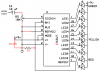
The circuit is attached, and here are the components I used:
1 x 10k Linear Taper Rotary Potentiometer
2 x 10uF 100V 85°C ELECTROLYTIC CAPACITOR (is positive the longer lead - the opposite side of the capacitor to where the grey line is)
2 x 1uF 25V TANTALUM CAPACITOR
1 x LM3915
1 x LM386
various 1/4W resistors (not all of them the exact values, but I've used a couple of resistors in series to add up to close the required resistance)
I purchased all these components off eBay to make this one circuit, and wasn't too happy when I wired it all up and it didn't work lol.
So basically, are my components correct? and is the circuit good for the desired vu meter?
Again, this isn't my circuit, and I'm not trying to claim it to be..
Thanks
Denno
When I applied the 9V, the LED's would light up, and the sequentially turn off. I couldn't get any response through the mic to show up in the LED's at all. I took it apart and re-wired it, but again, nothing..
I'm not sure if I'm using the right components either though? Just from looking at the schematics, I got the correct numbered components, but not sure if they're exactly what is needed or not?
The circuit is attached, and here are the components I used:
1 x 10k Linear Taper Rotary Potentiometer
2 x 10uF 100V 85°C ELECTROLYTIC CAPACITOR (is positive the longer lead - the opposite side of the capacitor to where the grey line is)
2 x 1uF 25V TANTALUM CAPACITOR
1 x LM3915
1 x LM386
various 1/4W resistors (not all of them the exact values, but I've used a couple of resistors in series to add up to close the required resistance)
I purchased all these components off eBay to make this one circuit, and wasn't too happy when I wired it all up and it didn't work lol.
So basically, are my components correct? and is the circuit good for the desired vu meter?
Again, this isn't my circuit, and I'm not trying to claim it to be..
Thanks
Denno
") .
.