zachtheterrible
Active Member
Hi all, I've got an LM3914 wired up to an RF module receiver's RSSI output, so I can see the signal strength. I made this circuit before I put it on a PCB with the ol' breadboard and I had no problems with it. I simulated the RSSI output of the RF IC with a potentiometer and it worked beautifully.
Now though, if i calibrate the 10 LED bargraph to be right in the middle and I turn on and off the transmitter, just one LED of the 10 LED bargraph will barely flicker. The weird thing is this: When I use my voltmeter's probe to see what the input voltage is on pin 5, 3 of the LEDs on the bargraph light up, and if I turn the transmitter on and off, those LEDs will respond accordingly.
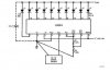
This leads me to believe I'm having some sort of oscillation problem or something. I would use a 2.2uf cap just like in the picture, but the LEDs are less than an inch from the LM3914. It only says to use it if the LEDs are more than 6" away. Should I decouple pin 5?
My supply voltage is 6V by the way.
I'd experiment with my circuit, but it's already on PCB, and I hate soldering and desoldering things on a PCB.
Now though, if i calibrate the 10 LED bargraph to be right in the middle and I turn on and off the transmitter, just one LED of the 10 LED bargraph will barely flicker. The weird thing is this: When I use my voltmeter's probe to see what the input voltage is on pin 5, 3 of the LEDs on the bargraph light up, and if I turn the transmitter on and off, those LEDs will respond accordingly.
This leads me to believe I'm having some sort of oscillation problem or something. I would use a 2.2uf cap just like in the picture, but the LEDs are less than an inch from the LM3914. It only says to use it if the LEDs are more than 6" away. Should I decouple pin 5?
My supply voltage is 6V by the way.
I'd experiment with my circuit, but it's already on PCB, and I hate soldering and desoldering things on a PCB.
")
