Continue to Site

Welcome to our site!

Electro Tech is an online community (with over 170,000 members) who enjoy talking about and building electronic circuits, projects and gadgets. To participate you need to register. Registration is free. Click here to register now.

  • Welcome to our site! Electro Tech is an online community (with over 170,000 members) who enjoy talking about and building electronic circuits, projects and gadgets. To participate you need to register. Registration is free. Click here to register now.

LM339 comparator issues

Status
Not open for further replies.

siyom

Member
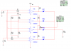
I'm having problems with the LM339 comparator.I know there's dozens of questions about this device but none clears the air for me.
I know its an open collector output and needs pull up resistors to set it to high but here's my problem.I have the pull up,but the output is always set at 1.7V even when i use a different comparator.
The inputs Voltage V+ dependa on the intensity of the ambient light and vary from 0-4.8V and am supplying the comparator with 5V,I know the inputs shouldnt go too close to the supply magnitude but they rarely go that far.
Even if the input V+ goes to zero the output still stays at 1.7V its only goes to zero when i manually ground the input V+
Please help
 
Last edited:
Welcome to ETO.

I am sure someone will ask to see your actual schematic for the circuit, so let me be the first.

John
 
1.7V is a strange voltage. Let me be the second to ask for a schematic.
Even if the input V+ goes to zero the output still stays at 1.7V its only goes to zero when i manually ground the input V+
What? 0V or ground?
 
In the actual circuit i used 2200 ohm for the pull-ups.The multisim simulation works perfectly but its the actual circuit that's giving me problems.
 

Attachments

  • circuit.png
    circuit.png
    34.2 KB · Views: 621
  • circuit.png
    circuit.png
    17.1 KB · Views: 448
Last edited:
Probably an error. One ohm resistor for R4,5,7. No!
R5,6,7 are not pulled up to 5V.

Please change R4,5,6,7 to 180 ohms. Connect all 4 resistors so then are from 5V to output.
Short out R3. (All LEDs go to ground.)
Now if the output is low (about 0 volts) the LED will be off because the IC will short out the LED.
Now when the output is high it will be about 1.5volts because the current will flow from 5V, through the resistor to the LED. Because the LED turns on and makes light at about 1.5V you will only see 1.5V at the output of the IC. (That is partly why you only see 1.7V now)
 
2200 is too large of a resistance for a 5 volt circuit. Your only allowing approximately 1.2 mA to flow through the LED and you might not see it energized without the aid of a darkened room. Decrease that resistance to allow about 10-20 mA to flow.
 
I've changed the resistor value to 100 ohms,now the circuit seems to be working slighltly better.The only problem now is that when the V+ input is zero the output pin has a voltage of 2.3V instead of just zero which is still high enough to be detected by a microcontroller.
 
Last edited:
So your using the comparator's output for an input to a microcontroller...

What is considered a low and what is considered a high for your microcontroller?

Leaving the microcontroller out of the conversation is not cool.
 
Last edited:
I'll be using the standard arduino board with an Atmega328.Apparently a logic low should be below 2.1V,and logic high should be 2.6V
Still a bit too risky as it lies in the undefined zone could be read as a high or a low.
 
At first, just a comparator. Then we find LEDs. Now a micro. What next?
From what little I can find out, there are LEDs from the output of the comparator to ground (or LEDs to a 180 ohm resistor to ground).
If you connect a LED from output to ground you can not get a voltage above the turn on voltage of the LED. But I don't really know what you have.
 
I'll be using the standard arduino board with an Atmega328.Apparently a logic low should be below 2.1V,and logic high should be 2.6V
Still a bit too risky as it lies in the undefined zone could be read as a high or a low.

Here is a comparison of your way, and a better way. I get a voltage swing of ~5V, and more current to the LED.
 

Attachments

  • DF51.jpg
    DF51.jpg
    330.2 KB · Views: 278
Last edited:
Why not look at the very low minimum output current of the LM339 comparator? It is only 6mA when the output voltage might be as high as 1.5V!
Then the resistor has a voltage drop of 3.5V so its minimum value is 3.5V/6mA= 583 ohms which is not a standard value. Use 620 ohms.
If the LED is a 1.8V red one then its current is (5V - 1.8V)/620 ohms= 5.2mA which is not very bright.
The LED might still glow a little when the LM339 output goes low and reduces its voltage to 1.5V.
 
In the actual circuit i used 2200 ohm for the pull-ups.The multisim simulation works perfectly but its the actual circuit that's giving me problems.

Hello,


You should define your circuit needs a little more carefully. Parts of your circuit do not make sense, for example the two resistors that connect from 5v to ground dont appear to be doing anything useful. Also, a 0v battery doesnt do anything so is that a sensor, or are some of the resistors sensors? You need to clarify this stuff.

Secondly, it's best to drive an LED 'on' when the output of the comparator goes LOW. That means you can connect a single resistor to the LED in series with it. The anode of the LED would go to +5v. If you also need to detect the logic state with an external circuit (like the uC board) then also use a pullup resistor like 4.7k which will provide the external circuit with the full logic swing of some low voltage like 0.5v up to 5v.
To get the output of the comparators to go low instead of high, simply swap the input terminals.

Thirdly, add some hysteresis to the comparators so there is no wild oscillation at levels close to the trip points.

Fourth and to repeat here, clarify what is a sensor and what is not, and what you want this circuit to do overall being very detailed about which LED's should light up for what sensor conditions.
 
Status
Not open for further replies.

Latest threads

New Articles From Microcontroller Tips

Back
Top