spacewaster
New Member
Hi, everyone
I'm new here, and as you are about to see, my nic is pretty apt! I can put other people's designs together, but ask me to create and I will look very blankly back at you.
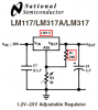
I've been using a LM317 circuit to get an 18V DC 1A input down to 9VDC. From what I can tell, it's a standard 317-type circuit, using a few caps between + and - "rails", a 2k4 resistor into ADJ and a 390R between ADJ and OUT to get it down to 9V.
The output needs have increased, and now the input is going to be 19V DC and 3.68A- an old laptop supply. I believe that would cause the 317 terminal distress.
Looking at the data sheets, the LM338 should cope admirably with some spare overhead.
Is it possible to reuse the principles of the 317's circuit, and how do I go about calculating the cap and resistor values?
Please be gentle...
SpaceWaster.
I'm new here, and as you are about to see, my nic is pretty apt! I can put other people's designs together, but ask me to create and I will look very blankly back at you.
I've been using a LM317 circuit to get an 18V DC 1A input down to 9VDC. From what I can tell, it's a standard 317-type circuit, using a few caps between + and - "rails", a 2k4 resistor into ADJ and a 390R between ADJ and OUT to get it down to 9V.
The output needs have increased, and now the input is going to be 19V DC and 3.68A- an old laptop supply. I believe that would cause the 317 terminal distress.
Looking at the data sheets, the LM338 should cope admirably with some spare overhead.
Is it possible to reuse the principles of the 317's circuit, and how do I go about calculating the cap and resistor values?
Please be gentle...
SpaceWaster.