Dirk.S
New Member
Hello Everyone
I hope that you all are doing really well. The project that I'm busy with is a little battery charger that will disengage when a set voltage is reached and engage again when the battery is drained to a certain point. I'm basing my design on the circuit I've gotten from the following website:
https://electronics-diy.com/automatic-battery-charger-2.php
with a closeup of the circuit part which will disengage and engage the charging process over here:
https://electronics-diy.com/schematics/1155/akucharger_schematics.jpg
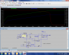
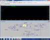
Now this circuit listed above needs a power supply to drive it so I've consulted the LM317 datasheet and came up to the point of the lab power supply circuit as can be seen from the attached picture below or if you have the datasheet on page 8 of the datasheet.

The reason I thought that I would go with this specific arrangement is that I could limit the current the way that I would like to i.e. to charge the battery attached at a certain current (Lead acid battery). Now I've see in the picture and in the datasheet that I will need to supply a negative 10 V to the transistors that goes to the adjust leg of the LM317.
The datasheet states the following:
To provide current limiting of IO to the system ground, the source of the FET must be tied to a negative voltage below - 1.25 V.
So I thought that I would use a secondary 12V winding from the transformer I hope to use to power the another circuit which inverts the 12V to a negative 12V which I aim to feed into this point. The voltage inverting circuit I found over here:
**broken link removed**
I just wanted to find out if this would work or whether it would be a bust. I've put the circuit on eagle (also attached below) and want to continue with the PCB design but don't want to continue if I'm wrong here. Your inputs are greatly appreciated, thank you in advance.

I hope that you all are doing really well. The project that I'm busy with is a little battery charger that will disengage when a set voltage is reached and engage again when the battery is drained to a certain point. I'm basing my design on the circuit I've gotten from the following website:
https://electronics-diy.com/automatic-battery-charger-2.php
with a closeup of the circuit part which will disengage and engage the charging process over here:
https://electronics-diy.com/schematics/1155/akucharger_schematics.jpg
Now this circuit listed above needs a power supply to drive it so I've consulted the LM317 datasheet and came up to the point of the lab power supply circuit as can be seen from the attached picture below or if you have the datasheet on page 8 of the datasheet.
The reason I thought that I would go with this specific arrangement is that I could limit the current the way that I would like to i.e. to charge the battery attached at a certain current (Lead acid battery). Now I've see in the picture and in the datasheet that I will need to supply a negative 10 V to the transistors that goes to the adjust leg of the LM317.
The datasheet states the following:
To provide current limiting of IO to the system ground, the source of the FET must be tied to a negative voltage below - 1.25 V.
So I thought that I would use a secondary 12V winding from the transformer I hope to use to power the another circuit which inverts the 12V to a negative 12V which I aim to feed into this point. The voltage inverting circuit I found over here:
**broken link removed**
I just wanted to find out if this would work or whether it would be a bust. I've put the circuit on eagle (also attached below) and want to continue with the PCB design but don't want to continue if I'm wrong here. Your inputs are greatly appreciated, thank you in advance.
") ]
]