Continue to Site

Welcome to our site!

Electro Tech is an online community (with over 170,000 members) who enjoy talking about and building electronic circuits, projects and gadgets. To participate you need to register. Registration is free. Click here to register now.

  • Welcome to our site! Electro Tech is an online community (with over 170,000 members) who enjoy talking about and building electronic circuits, projects and gadgets. To participate you need to register. Registration is free. Click here to register now.

LM317 adjustable voltage reg problem.

Status
Not open for further replies.
Hi all.

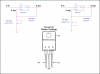
I'm making an adjustable voltage circuit from a LM317 now I've done this before without any issue's but now I'm blowing pott's like there tuppence happeny!!!

I've used the circuit as per the **broken link removed** but when I adjust the pott to the end of it's turns it fizzles.

I'm unsure why this is happening but it's obvious I'm doing something wrong!!!

Any suggestions?? I now have to purchase some more 5K potts:confused:

Cheers Mark
 
You are absolutely sure that you have the pin out correct. The most common cause of what you describe is having for example incorrect connections.

Ron
 
You need a minimum load of 5mA or else the thing wont regulate. You also need a decoupling cap on the input as close to the pins as you can get (and obviously one on the output). 10uF on both sides should be enough. The decoupling thing is also applicable to the 7805/7808/7812 etc parts.
 
hi Mark,
Look at this image for the connections.

Add the required decoupling capacitors on the input and output.
 

Attachments

  • AAesp02.gif
    AAesp02.gif
    6.6 KB · Views: 6,756
A common error that can cause this is following the topology of the data sheet figure without due regard to the actual pinout. If you make this mistake, your pot is connected to the output. This happens so often that I wish they'd redraw the figure so it matches the pinout of the device.
 
Hi Guys

Thanks for the advice on this I will have to give it another go.I did follow the data sheet for location on the pin outs.I may have a short or something on the board but it only happens when the pot is at it's max turn.

The caps on the diagram on the data sheet are these the said **broken link removed** (0.1uf & 1uf) or are these there other reasons.

I don't suppose the POTT. can be wired wrong can it? just covering all the avenues!!

Cheers Mark
 
The circuit you have should resemble the attached. The 5 K pot can be configured a few ways as can be seen. So Max is a matter of how it is wired. The only way a pot like this will actually burn up or cook is if there is excessive current through it. Also note in the LM317 pin out image that the tab is also Vout so if anything is on the tab like a heat sink it is at Vout potential. The attached is sans caps as I doubt a cap is the problem with your symptoms.

Ron
 

Attachments

  • LM 317.png
    LM 317.png
    24.5 KB · Views: 682
What output voltage do you have? With the pot set close to max (i.e.the wiper shunts most of it) the 240 ohm resistor will pass ~4mA per volt of output. So at 25V output, say, the pot current will be ~ 100mA. As that is going through a tiny part of the resistance track it may well be enough to cook it, especially if the pot is a miniature type. Could you make the resistor, say, 1k? (That would, of course, reduce the adjustment range the pot provides).
 
You need a minimum load of 5mA or else the thing wont regulate.
Absolutely not!
Only "typical and better" LM317 ICs need a current of 5mA. Weak but passing ones need 10mA provided by changing the 240 ohm resistor (used for an expensive LM117) to 120 ohms and cutting the value of the pot in half.

The datasheet does not show the correct schematic for the voltage-setting pot. You probably connected it so it shorts the output. My schematic is correct.

ALL circuits in the datasheet (and all over the internet) show the 240 ohm resistor used with the more expensive LM117. If 240 ohms is used with a weak but passing LM317 then its output voltage rises without a load (no regulation) as explained in the datasheet.
 

Attachments

  • LM317.PNG
    LM317.PNG
    12 KB · Views: 4,233
What output voltage do you have? With the pot set close to max (i.e.the wiper shunts most of it) the 240 ohm resistor will pass ~4mA per volt of output. So at 25V output, say, the pot current will be ~ 100mA.

Absolutely not!
The current in the pot is the micro-amps from the ADJ pin plus the 5mA from the 240 ohm resistor. 5.005mA is nowhere near the 100mA you said.

When the pot is set to a low voltage (its resistance is low, not high) then it has a current of only 5.005mA, not 100mA.
With the output voltage set to 25V then if the current in the 5k pot is 100mA then it has 500V (!) across it.
 
The current in the pot is the micro-amps from the ADJ pin plus the 5mA from the 240 ohm resistor.
Can you please explain where you get the 5mA figure from? Correct me if I'm wrong (and I'm sure you or some other kind soul will :D), but if Vout = 25V (perhaps due to a delayed response by the regulator or a voltage spike from interference or feedback from an inductive load, or as a result of a poor connection between the pot R2 and the adjustment terminal of the regulator) the current to ground via R1 and R2 is Vout/(R1 + R2). If R2 is set at the extreme position where most of its resistance is bridged by the wiper then R2 ~ 0. So the current is 25V/240 ohm = ~ 100mA, albeit perhaps briefly. That current flows through R1 and the unbridged part of R2 and may be enough to blow R2.
 
Last edited:
The 240 ohm resistor for an LM117 has 1.25V across it. Then its current is 1.25/240= 5.2mA.
The 120 ohm resistor for an LM317 also has 1.25V across it. Then Ohm's Law says its current is 10.4mA.
The amount of power in the resistors is almost nothing.

If the pot is set to a very low resistance then the output voltage of the regulator will be close to only 1.25V (the lowest output voltage of an LM317) so the resistors will not get warm.
The input and output capacitors stop voltage spikes.
 
Thanks for the explanation.
The amount of power in the resistors is almost nothing.
If the pot is set to a very low resistance then the output voltage of the regulator will be close to only 1.25V (the lowest output voltage of an LM317) so the resistors will not get warm.
That's the theory, but the OP's pots (and Ziddik's) clearly were getting warm. How do you explain that?
 
Absolutely not!
Only "typical and better" LM317 ICs need a current of 5mA. Weak but passing ones need 10mA provided by changing the 240 ohm resistor (used for an expensive LM117) to 120 ohms and cutting the value of the pot in half.

The datasheet does not show the correct schematic for the voltage-setting pot. You probably connected it so it shorts the output. My schematic is correct.

ALL circuits in the datasheet (and all over the internet) show the 240 ohm resistor used with the more expensive LM117. If 240 ohms is used with a weak but passing LM317 then its output voltage rises without a load (no regulation) as explained in the datasheet.

Cheers Audioguru!!
 
Thanks for the explanation.

That's the theory, but the OP's pots (and Ziddik's) clearly were getting warm. How do you explain that?

Many people connect parts backwards or wrongly. They measure voltages incorrectly so maybe they are too high.
I have purchased LEDs here that were made in Ziddick's country and most were defective. Maybe most parts in Ziddick's country are defective.
 
Status
Not open for further replies.

Latest threads

New Articles From Microcontroller Tips

Back
Top