Continue to Site

Welcome to our site!

Electro Tech is an online community (with over 170,000 members) who enjoy talking about and building electronic circuits, projects and gadgets. To participate you need to register. Registration is free. Click here to register now.

  • Welcome to our site! Electro Tech is an online community (with over 170,000 members) who enjoy talking about and building electronic circuits, projects and gadgets. To participate you need to register. Registration is free. Click here to register now.

LM2917 problems

Status
Not open for further replies.

matt83

New Member
Hey,

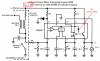
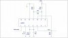
I am trying to convert a 10-30 Hz pulse train (varying between 0 and 10V) to voltage with a LM2917N circuit (see attached scheme). I have two problems;

1. The output voltage isn't right according to the values of C1 and R1. For example, a 12 Hz pulse train yields 3.3V output, 18 Hz yields 5.2V and so on.

2. The output voltage is "capped" at 6 Volt, I'm unable to get it to increase beyond this value no matter what voltage I feed the circuit with or what values I use on the components.

While 1) is mostly annoying and can be fixed by simply changing the value of R1 I would still like it to work according to the formula in the data sheet (Vout = Vsource * frequency * R1 * C1).
Problem 2) is worse though and I can't seem to find a solution. Can it have anything to do with the built-in zener diode? It is also strange that it is capped at 6V no matter if I use 12, 15 or 18V to feed the LM2917.

If anyone could shed some light on this I would appriciate it deeply :)

Thanks
 

Attachments

  • test2.JPG
    test2.JPG
    60.3 KB · Views: 1,485
Last edited:
The zener voltage is your Vsource (VCC). According to the datasheet, this should be 7.56V (typical), and there is no tolerance specified. Note 3 is also relevant:
Note 3: VOH is equal to 3⁄4 x VCC − 1 VBE, VOL is equal to 1⁄4 x VCC − 1 VBE therefore VOH − VOL = VCC/2. The difference, VOH − VOL, and the mirror gain, I2/I3,
are the two factors that cause the tachometer gain constant to vary from 1.0.
1VBE is approximately 0.7V. I am surprised you are getting 6V out for VOH.
 
Huge thanks, now it makes sense. All calculations match (well enough at least) when using 7.56V as Vcc.

Isn't VOH the voltage on pin 2? The only reason I can see for the Vout cap at 6V would be if it is somehow related to Input Common-Mode Voltage on the OP AMP/Comparator which is listed as Vcc-1.5V Max.
 
Your circuit is nearly the same as the tachometer in the datasheet.
The output opamp is powered from the 7.6V zener diode and its max output voltage is about 6.7V.
The output emitter-follower transistor has a base-emitter voltage drop of 0.7V so the max output voltage of the circuit is +6.0V.
 

Attachments

  • LM2917 tach.PNG
    LM2917 tach.PNG
    38.3 KB · Views: 5,542
audioguru said:
Your circuit is nearly the same as the tachometer in the datasheet.
The output opamp is powered from the 7.6V zener diode and its max output voltage is about 6.7V.
The output emitter-follower transistor has a base-emitter voltage drop of 0.7V so the max output voltage of the circuit is +6.0V.
Hi AG, how do you know the max output of the op amp is 6.7V? I was just going by the note in the datasheet:
Note 3: VOH is equal to 3⁄4 x VCC − 1 VBE
. Thsi equation results in VOH~5V.:confused: Maybe the datasheet is being conservative?
 
Roff said:
Hi AG, how do you know the max output of the op amp is 6.7V? I was just going by the note in the datasheet: . Thsi equation results in VOH~5V.:confused: Maybe the datasheet is being conservative?
The output of the opamp is a single transistor emitter-follower, not a darlington like real opamps. So its output high is about 0.9V below the supply, not a percentage.
 
audioguru said:
Your circuit is nearly the same as the tachometer in the datasheet.
The output opamp is powered from the 7.6V zener diode and its max output voltage is about 6.7V.
The output emitter-follower transistor has a base-emitter voltage drop of 0.7V so the max output voltage of the circuit is +6.0V.

Thank you :)

I will change the range of Vout to 0-5V, but I would like to be able to double or triple the output as well (0-10 and 0-15V respectively). Doubling seems doable with a charge pump dc-dc voltage converter (for example Maxim MAX1680) but are there any straightforward solutions to get 0-15V out?
 
A single supply opamp like a dual LM358 can have an output voltage of 0V to 15V at up to 10mA typically when its supply voltage is 16.5V.
 
I haven't used the LM2917 or the 2907, but I would think you could get 15V out of an LM2907. You would need 18 to 20 volts, and it would need to be regulated.
 
i would like to convert frequency to voltage. i am using lm2917 14 pins to do it but i have some problem. i am not sure how to connect mt input since is it ranging from 1 to 3 V. :(
 
kokhc said:
i would like to convert frequency to voltage. i am using lm2917 14 pins to do it but i have some problem. i am not sure how to connect mt input since is it ranging from 1 to 3 V. :(
The LM2917 has two inputs. Page 10 of the datasheet shows how pin 11 can be biased with a diode and resistor to +0.7V then when the input pin 1 rises higher than +0.7V the IC will count one pulse. Use a voltage divider instead of the diode to have a higher threshold voltage (+2V).
 
Status
Not open for further replies.

Latest threads

New Articles From Microcontroller Tips

Back
Top