Continue to Site

Welcome to our site!

Electro Tech is an online community (with over 170,000 members) who enjoy talking about and building electronic circuits, projects and gadgets. To participate you need to register. Registration is free. Click here to register now.

  • Welcome to our site! Electro Tech is an online community (with over 170,000 members) who enjoy talking about and building electronic circuits, projects and gadgets. To participate you need to register. Registration is free. Click here to register now.

LM2907 shift lamp problems

Status
Not open for further replies.

indecided

Member
HI there. I'm new to this forum, came across it through a search from google.

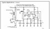
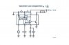
Anyways.. I'm building this shift lamp, which design is based on the LM2907's reference design but goes to a LM741 comparator.

Problem here is, the reference design is for a 8 cylinder engine.

my car is a steady 'ol 4 cyl. Now, i'm not sure if that's really the point.

For example at 1000rpm i should be getting 1v output. however... there seems to have been a mixup and i get roughly a tenth of the original voltage, roughly about 0.10 - 0.11v.
same goes all the way up to 6000rpm.

Now, based on the reference diagram, i've come to the conclusion that i'd probably need to change a resistor or two to compensate for the differences in application. but... i can't figure out which one.

enclosed is the design i'm following. i'm at wits end now...
 

Attachments

  • shiftlight.pdf
    7.7 KB · Views: 2,411
this is the reference design.
 

Attachments

  • untitled_213.jpg
    untitled_213.jpg
    23.5 KB · Views: 3,690
Hi Indecided,
I see a few things wrong that can cause your problem:
1) If you look closely at your "reference" circuit, it has a 7.5V zener diode at pin 9 of the LM29xx. That zener diode is included inside an LM2917, but your LM2905 doesn't have one. Add one to your circuit and it will probably work much better.
2) The circuit that you are using has an extra opamp-comparator and relay driver. Why is it using a lousy old 741 opamp when the LM2905 has a very good comparator and powerful output transistor built right in?
The 741 requires its inputs to be at least 3V away from its positive supply and ground (its negative supply), which is called its common-mode input voltage range. Your circuit has its inputs too close to ground. The opamp/comparator inside your LM2905 works very well with its inputs all the way down to ground.
The 741 is guaranteed to drive a 2Kohm load to only 10V, when using a dual 15V supply. That is a loss of 5V with a load current of only 5mA. The output transistor inside the LM2905 has a low loss and can drive a load current of 50mA.
3) The datasheet shows a 100Kohm resistor at pin 3 for an 8 cylinder engine and a 133Kohm one for 6 cylinders. Therefore use 200Kohms for 4 cylinders.
4) In addition to getting rid of the old 741 opamp, the LM2905's datasheet shows how to connect its opamp/comparator as a speed switch, which is what you want. Use a 10Kohm pot instead of its 5Kohm resistors to adjust its trip point. It might be accurate enough without a zener diode. It is using the 8-pin IC, the pin numbers are different if yours has 14 pins. Their circuit is here:
 

Attachments

  • speed_switch.jpg
    speed_switch.jpg
    27.7 KB · Views: 2,955
Hi there audioguru.
s
audioguru said:
Hi Indecided,
I see a few things wrong that can cause your problem:
1) If you look closely at your "reference" circuit, it has a 7.5V zener diode at pin 9 of the LM29xx. That zener diode is included inside an LM2917, but your LM2905 doesn't have one. Add one to your circuit and it will probably work much better.
- note taken :)

2) The circuit that you are using has an extra opamp-comparator and relay driver. Why is it using a lousy old 741 opamp when the LM2905 has a very good comparator and powerful output transistor built right in?
The 741 requires its inputs to be at least 3V away from its positive supply and ground (its negative supply), which is called its common-mode input voltage range. Your circuit has its inputs too close to ground. The opamp/comparator inside your LM2905 works very well with its inputs all the way down to ground.
The 741 is guaranteed to drive a 2Kohm load to only 10V, when using a dual 15V supply. That is a loss of 5V with a load current of only 5mA. The output transistor inside the LM2905 has a low loss and can drive a load current of 50mA.
- i was unaware of the 741's requirements... the original voltage designed for should have been... about 2.84v at 4000rpm. however... how do i harness the op-amp/comparator when utilizing a voltage output?


3) The datasheet shows a 100Kohm resistor at pin 3 for an 8 cylinder engine and a 133Kohm one for 6 cylinders. Therefore use 200Kohms for 4 cylinders.
- That's my probelm here. I'm currently using a 250k pot.. and at full resistance, i get about 0.6 volts at 3000RPM. should be about 2v+..
Here i have experimented with a 1meg pot. I get the voltage i want, however, the latency experienced is unacceptable (i have to wait for the voltage to rise and fall when i throttle rapidly)

4) In addition to getting rid of the old 741 opamp, the LM2905's datasheet shows how to connect its opamp/comparator as a speed switch, which is what you want. Use a 10Kohm pot instead of its 5Kohm resistors to adjust its trip point. It might be accurate enough without a zener diode. It is using the 8-pin IC, the pin numbers are different if yours has 14 pins. Their circuit is here:
- The problem however.. is that is a speed switch. Useful for a door actuator lock at speed, or a speed limiter. The problem here however, is that i need to connect it as a REV comparator. not a speed.. so when I change gear i get notification.. not at a certain speed!

thanks! can you point me in the.. right direction?
 
Hi Indecided,
Did adding the zener diode help your circuit?
On your circuit, you are probably measuring the voltage that is too low at the output of the 741, which doesn't work. You should measure the voltage at the output of the LM2905 pins 5 and 10. Using 100K ohms at pin 3, its output should be 2.0V at 4000 RPM. Using 200K, it should be 4.0V. Reduce the value of the capacitor at pin 3 if it is too slow to respond, to 0.47uF or less.

The Speed Switch circuit connects to your engine, not your wheels, so it switches its output at a set RPM. Isn't that what you want? It will switch a relay, or an LED in series with a current-limiting resistor.
 
Hi audioguru... I just picked up a couple of zeners. will be trying them later today...

I measure the voltage right off pin 5, and the car body for earth.

I hope i get the desired results later. rebuilding the LM2907 portion alone.

The speed switch...i believe it is configured for speed.. but i will try it out as well.

Thanks! :) Will keep you updated.

audioguru said:
Hi Indecided,
Did adding the zener diode help your circuit?
On your circuit, you are probably measuring the voltage that is too low at the output of the 741, which doesn't work. You should measure the voltage at the output of the LM2905 pins 5 and 10. Using 100K ohms at pin 3, its output should be 2.0V at 4000 RPM. Using 200K, it should be 4.0V. Reduce the value of the capacitor at pin 3 if it is too slow to respond, to 0.47uF or less.

The Speed Switch circuit connects to your engine, not your wheels, so it switches its output at a set RPM. Isn't that what you want? It will switch a relay, or an LED in series with a current-limiting resistor.
 
Hi audioguru,

just added the 7.5v zener and volia.. the circut simply stops working properly. it does exhibit a breakdown of 7.5v at it's cathode, though.

at wits end now :|

audioguru said:
Hi Indecided,
Did adding the zener diode help your circuit?
On your circuit, you are probably measuring the voltage that is too low at the output of the 741, which doesn't work. You should measure the voltage at the output of the LM2905 pins 5 and 10. Using 100K ohms at pin 3, its output should be 2.0V at 4000 RPM. Using 200K, it should be 4.0V. Reduce the value of the capacitor at pin 3 if it is too slow to respond, to 0.47uF or less.

The Speed Switch circuit connects to your engine, not your wheels, so it switches its output at a set RPM. Isn't that what you want? It will switch a relay, or an LED in series with a current-limiting resistor.
 
Hi Indecided,
Previously I was talking about an LM2905, but I really meant LM2907. Sorry.
It doesn't work? Now with the zener, it is exactly the same as your reference circuit.
Are you using the 14 pin version of the LM2907? The 8 pin version won't work with "breaker points".
Are you sure that your car has "breaker points"?
 
Hi there audioguru.

yes..i have built it to spec as per reference circut. with a 7.5v 1w zener at pin 9, i measure 7.5v at pin 9. but no good :D I am using the 14 pin.

okay..breaker points. what i did here...i used my tach output, which is the negative terminal from the ignition coil. i used to have a small tachometer using the same output, which is why i know it works..


audioguru said:
Hi Indecided,
Previously I was talking about an LM2905, but I really meant LM2907. Sorry.
It doesn't work? Now with the zener, it is exactly the same as your reference circuit.
Are you using the 14 pin version of the LM2907? The 8 pin version won't work with "breaker points".
Are you sure that your car has "breaker points"?
 
Hi Indecided,
What could cause your problem?
Open or shorted capacitors.
Wrong value resistors.
Open or shorted diode at pin 11 (measure its voltage).
Defective LM2907.
 
Audioguru,

have just retested the circut.

I can attain 4.5v at 3000RPM now...

BUT.... that is with my headlamps and air conditioning turned on.

otherwise.. the voltage lingers around 0.3V normally.

What now? am i supposed to come to a conclusion that when sufficient load is present only then will the circut be accurate?

I don't see the link.

thanks!

audioguru said:
Hi Indecided,
What could cause your problem?
Open or shorted capacitors.
Wrong value resistors.
Open or shorted diode at pin 11 (measure its voltage).
Defective LM2907.
 
Hi Indecided,
Since your circuit works OK when the car's electric loads are on, then maybe its alternator voltage regulator outputs a lot of electrical noise without much load.
The circuit's 10K and 20K voltage divider make it very sensitive to noise from the points. Change the 10K resistor to 100K.
 
audioguru said:
Hi Indecided,
Since your circuit works OK when the car's electric loads are on, then maybe its alternator voltage regulator outputs a lot of electrical noise without much load.
The circuit's 10K and 20K voltage divider make it very sensitive to noise from the points. Change the 10K resistor to 100K.

thanks audioguru for ur feedback! i really appreciate it..

going down to the car soon to test it out.. if only i had a bench regualtor :)
 
audioguru said:
Hi Indecided,
Since your circuit works OK when the car's electric loads are on, then maybe its alternator voltage regulator outputs a lot of electrical noise without much load.
The circuit's 10K and 20K voltage divider make it very sensitive to noise from the points. Change the 10K resistor to 100K.

Audioguru, just to clarify, u mean the 10k resistor that bridges the breaker point input right? not the 12v rail one which goes with the 1N4001?


ps : the circut wont' work with the zener in. any idea why?
 
Hi Indecided,
Yes, change the 10K resistor that connects to the breaker points to 100K, to make the circuit's input less sensitive to electrical noise from the points.

Assuming that there is a lot of electrical noise without much load on the alternator, without the zener the circuit's supply voltage is bouncing around with the noise, making it less sensitive. With the zener, the supply noise is reduced so that the circuit works properly, however its input sensitivity is too high to handle that much noise on its input. You could also add a 100uF capacitor across the zener to filter the supply noise even more.
 
audioguru said:
Hi Indecided,
Yes, change the 10K resistor that connects to the breaker points to 100K, to make the circuit's input less sensitive to electrical noise from the points.

Assuming that there is a lot of electrical noise without much load on the alternator, without the zener the circuit's supply voltage is bouncing around with the noise, making it less sensitive. With the zener, the supply noise is reduced so that the circuit works properly, however its input sensitivity is too high to handle that much noise on its input. You could also add a 100uF capacitor across the zener to filter the supply noise even more.

Hi there audioguru.

Put in the 100k resistor.

Same results...

Hmm.. any other ideas for as what i can attribute this problem to?
 
Hi Indecided,
I think that it is time to connect an oscilloscope to your circuit at the car to see exactly what is going wrong.
 
audioguru said:
Hi Indecided,
I think that it is time to connect an oscilloscope to your circuit at the car to see exactly what is going wrong.

Audioguru, i wish that was an option. Being a regular hobbyist, I don't have an oscilloscope at my disposal.

the funny thing is, my external tachometer, which operates on a 555 pulsed, has no such problems at all.

:( and using the same wire. perhaps it's the way it reads the frequency..

or it's simply the zener diode. bah. LM2917's are hard to come by here.

going to troubleshoot a lil more...

thanks!
 
Hi audioguru,

pleased to announce that the problem has been solved! it turns out my power tap was dirty - it was from the ignition direct!

now that i tapped it from 12v battery direct (not practical for long-term usage though), i get all my expected voltage output! tsk.. dirty power lines.

However i still need your help... because the Vcc voltage fluctuates when the loads are applied (ie radiator fan, air-conditioning, headlamps), i would like to know the best way to stabilze the voltage so that my shift point will be the same.

as per my first diagram, i utilize a voltage divider network to get the voltage to compare for the LM741. when the loads turn on, this voltage fluctuates... and i think that will be a problem. how can i fix it firm?

Thanks lots!!

PS : or is there a better way to harness the internal op-amp/comparator of the 2907 for a tachometer output? (the one u pointed me to is for speed...ie wheels. not sure if it can be adapted)

indecided said:
audioguru said:
Hi Indecided,
I think that it is time to connect an oscilloscope to your circuit at the car to see exactly what is going wrong.

Audioguru, i wish that was an option. Being a regular hobbyist, I don't have an oscilloscope at my disposal.

the funny thing is, my external tachometer, which operates on a 555 pulsed, has no such problems at all.

:( and using the same wire. perhaps it's the way it reads the frequency..

or it's simply the zener diode. bah. LM2917's are hard to come by here.

going to troubleshoot a lil more...

thanks!
 
Can you beg, borrow, steal or make a CMOS or 555 variable frequency square-wave oscillator to feed it then?
Test it without the engine running.
 
Status
Not open for further replies.

Latest threads

Back
Top