Continue to Site

Welcome to our site!

Electro Tech is an online community (with over 170,000 members) who enjoy talking about and building electronic circuits, projects and gadgets. To participate you need to register. Registration is free. Click here to register now.

  • Welcome to our site! Electro Tech is an online community (with over 170,000 members) who enjoy talking about and building electronic circuits, projects and gadgets. To participate you need to register. Registration is free. Click here to register now.

LM 311N Voltage Comparator Question

Status
Not open for further replies.

elfvenlord

New Member
Hi

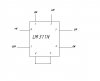
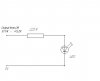
Im still trying to build a circuit using the LM 311N Voltage comparator but it never works out.So I've attached the pin layout that Im using.Could anyone tell me if I've got it right.

The comparator is supposed to compare the two voltages on pins 2 and 3 and then switch to either +V or 0V.Was hoping that I didn't have to use a -V.
 

Attachments

  • voltage_comparator.jpg
    voltage_comparator.jpg
    9.3 KB · Views: 659
are you using apull-up resistor on the output. I am pretty sure that the LM311 is an open-collector output.

If you dont use one then you want be measuing any voltage on the output.
 
O/C

Styx is right, comparators generally use open collector outputs, and you need to place a pullup resistor to VCC on the output. The LM311 is interesting in that it has an open emitter (pin 1, normally grounded) as well, useful for driving ground-referenced loads. Take a look at the datasheet for some examples. Here are some app. notes that help explain the differences between op-amps and comparators

https://www.electro-tech-online.com/custompdfs/2004/07/sloa067.pdf

**broken link removed**
 
When you say pull up resistor, do you mean a resistor in series with the load(as shown in the drawing below) or do you mean in parallel with the load i.e. a resistor between the output(pin 7) and 0V.I connected it up as shown in the drawing below and the LED didn't light up when the input voltages where compared.
I even had the +ve input at 4V and the -ve input at 1V and still it didn't light up the led.
Do you think It can operate on only a single supply?
If it can then maybe the IC is fried but I only just bought it,so guess not.
 

Attachments

  • lm311n_outut.jpg
    lm311n_outut.jpg
    9.4 KB · Views: 549
pullup resistor

When you say pull up resistor, do you mean a resistor in series with the load(as shown in the drawing below) or do you mean in parallel with the load i.e. a resistor between the output(pin 7) and 0V?

Neither exactly, though your first description comes closer. A resistor connected from the output (pin 7) to the positive supply is considered a "pull up" and would allow you to see the output swing from (approximately) ground to VCC with a multimeter.

Your output circuit (load) can take the place of a pull up resistor, with a few changes. Connect the point labeled "Output from 311 - +5.2B" to your positive supply, and connect the point labeled "0V" to the 311s' output. This completes the output circuit, and the collector is no longer "open".
 
:shock: Hold on I think I've just seen the light.SO the LM311N output doesn't switch to 5.2V but acts more like the collecter on a transistor and the current flows through the led,through the output(pin7) and to 0V.

So I would connect the led's anode to the +V and then its cathode to pin 7 through the resistor.
Am I on the right track?
 
:D Hurray


Thanks so much for your help styx and laroche73,its much appreciated.
 
Status
Not open for further replies.

Latest threads

New Articles From Microcontroller Tips

Back
Top