Electro Tech is an online community (with over 170,000 members) who enjoy talking about and building electronic circuits, projects and gadgets. To participate you need to register. Registration is free. Click here to register now.
Welcome to our site! Electro Tech is an online community (with over 170,000 members) who enjoy talking about and building electronic circuits, projects and gadgets. To participate you need to register. Registration is free. Click here to register now.
A pulse can be represented as a series of harmonicly related sine waves. If the harmonics are phase shifted relative to one another, the shape of the pulse is changed. The best result is obtained when the phase shift is linear.
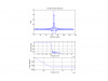
BTW, is that a real filter or theoritical? Such sharp cutoff in a linear phase filter is impressive.
A pulse can be represented as a series of harmonicly related sine waves. If the harmonics are phase shifted relative to one another, the shape of the pulse is changed. The best result is obtained when the phase shift is linear.
Expanding on that - any periodic wave consists of a series of harmonically related sinusoids. If the entire wave is delayed by t seconds, then the phase shift is of the fundamental is
Φ=(t/T1)*360 degrees, where T1 = 1/F1 = period of fundamental,
or
Φ1=t*F1*360 (fundamental).
Since the frequency of the 2nd harmonic =2*F1,
Φ2=t*2*F1*360 (2nd harmonic),
Φ3=t*3*F1*360 (3rd harmonic)
etc.
Note that the phase shift is a linear function of frequency.
BTW, is that a real filter or theoritical? Such sharp cutoff in a linear phase filter is impressive.
I'm guessing it's a finite impulse response (FIR) digital filter. Realizing that response in an infinite impulse response filter (such as an RLC filter) is basically impossible.
Linear phase is a RESULT of making a non-causal digital filter causal. Digital filters are inherently non-causal, however they can easily be shifted by N samples to become causal, hence linear phase shift, you're adding delay to make the filter causal.
A pulse can be represented as a series of harmonicly related sine waves. If the harmonics are phase shifted relative to one another, the shape of the pulse is changed. The best result is obtained when the phase shift is linear.
Expanding on that - any periodic wave consists of a series of harmonically related sinusoids. If the entire wave is delayed by t seconds, then the phase shift is of the fundamental is
Φ=(t/T1)*360 degrees, where T1 = 1/F1 = period of fundamental,
or
Φ1=t*F1*360 (fundamental).
Since the frequency of the 2nd harmonic =2*F1,
Φ2=t*2*F1*360 (2nd harmonic),
Φ3=t*3*F1*360 (3rd harmonic)
etc.
Note that the phase shift is a linear function of frequency.
So does this mean that the digital filter needs to preserve all the harmonics of the wave, so that the phase shift obtained is linear (because all harmonics are present) ?
Not necessarily. The purpose of some filters is to eliminate higher harmonics. In the time domain, it is usually desirable to preserve the general shape of the input wave, so the harmonics that remain after filtering need to have equal delay (linear phase shift). This means that the filter needs to have linear phase shift for all significant harmonics. What is significant depends on the application.
Thinking about this in the time domain and not discrete domain does not help your endeavor.
If you review your DSP you'll find that one of the primary advantages of a FIR filter (which is what you have shown) is they have linear phase shift. The reason for the linear phase shift is the idea of causality. Initially when the FIR filter is designed it depends on FUTURE values of time (non - causal), to solve this problem we simply shift the filter by N samples to force the filter to depend on past samples (causal). Intuitively this make sense as we cannot know future samples, but we can store past samples to use them later. This is the reason for the linear phase shift that is introduced into the system.
yes, but we also do not store past output values in an FIR Filter, we do that in an IIR Filter. Another condition is that the Filter zeros should show even/odd symmetry.. H(n) = +/-H(N-n). Whereas we do store past o/p values in an IIR Filter. So this makes the IIR Filter have not such a good phase linearity !
If you don't store past samples of your wave form I'm not sure exactly how you intend on filtering. Please review the equation posted below, you'll find its absolutely necessary to save your past samples. x(n) is the input into your filter, h(n) is the impulse response of your filter, and y(n) is the output of your filter.
Fourier series states that all signals can be represented as sums of sinusoids.
x(t) = A sin (wt + p)
If phase p is linear,
p=aw
Then
x(t) = A sin (w(t+a))
= A sin (wT)
where T = t+a
The importance is that no matter how many sinusoids your signals contain, all of them get shifted by the SAME delay a. As such, there is no distortion of the signal shape.
This site uses cookies to help personalise content, tailor your experience and to keep you logged in if you register.
By continuing to use this site, you are consenting to our use of cookies.

")