Electro Tech is an online community (with over 170,000 members) who enjoy talking about and building electronic circuits, projects and gadgets. To participate you need to register. Registration is free. Click here to register now.
Welcome to our site! Electro Tech is an online community (with over 170,000 members) who enjoy talking about and building electronic circuits, projects and gadgets. To participate you need to register. Registration is free. Click here to register now.
Its dc supply.i need to power a dual supply op-amp i found a circuit at this webpage http://www.armory.com/~rstevew/Public/PSUs/-vgen.html, its supplies a negative voltage which gets it from the positive Vcc but -Vcc has a 1.2V difference from the positive. I need to make -Vcc = +Vcc. Follow up question Do i need both -Vcc and +Vcc equal to make the op-amp work properly
If your input signal is ground reference, you need -5 volts minimum to operate the TL082, but you could operate with a single + supply by biasing the input at +5 volts. The MAX1681 will generate -5 volts from +5 volts.
I think they all do!
When is the last time you had +VCC and realized that your minus supply was exactly (-1)*Vcc..
Actually, if you look at the design of the typical opamp, there is nothing demanding that the supplies be equal, it is all about how much you need your output to swing.
TO reduce power dissipation, I often run asymetric supplies. In other words, if I have say +/-15V supplies but my circuit never goes below say -4, I will run the opamp on +15 and -5. But usually, there are only a couple of supply rails available in the system and so its easier just to use those and those are usually symetric.
In addition to the output swing, you have to consider the input common mode range. In the case of the TL082, the op amp is not guarenteed to work if the common mode is closer than 4 volts to the supply rails. That is why I recomment minimum -5 volt supply.
Im using this opamp configuration. So if used a fixed -5V and 10V Vccs i should have a amplitude of 10V? how about i lower the+Vcc to 9V having the -5V still fixed would i have an amplitude of 9V?
Im using this opamp configuration. So if used a fixed -5V and 10V Vccs i should have a amplitude of 10V? how about i lower the+Vcc to 9V having the -5V still fixed would i have an amplitude of 9V?
Your positive and negative supply provide a voltage range that the output of the op amp can span. Now, your actual output amplitude is predicted by your circuit design. If your circuit causes the output to equal or attempt to exceed the respective supply rail, then the op amp will saturate and hold the output "close" to the supply rail. How close depends on opamp - check the datasheet. But of course one can design the circuit to stay well within the supply range. Typically, one has an idea about what values the output voltage must span. Knowing this, one provides + and - supplies to the opamp that are large enough in magnitude to accomodate this. Clear as mud?
Perhaps you should explain exactly what you are trying to do and why?.
We may be able to make suggestions to make things easier - one obvious one is to generate an artifical split supply between the existing rails. So if your HT rail is 9V, you would have 9V (+ve rail), 4.5V (0V rail) and 0V (-ve rail). This is common practice with opamps, but depends somewhat on what you are trying to do.
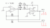
im trying to make a variable sawtoothwaveform using the opamp configuration above. This configuration has the characteristic that watever the Vccs inputted equals the amplitude outputted.
So if your HT rail is 9V, you would have 9V (+ve rail), 4.5V (0V rail) and 0V (-ve rail).
"This configuration has the characteristic that watever the Vccs inputted equals the amplitude outputted. "
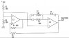
Not so. This is a clever circuit, but the output amplitude is dependent on the resistor values. If the output actually hits the rail, the circuit will hang. I will post a better configuration.
oH - oH, I was wrong, the output does vary with VCC because the first op amp (IC1) output varies the bias on the resistors. I changed the value of R3 because the output of IC2 swings too close to the rail.
This circuit can be used with a single supply voltage.
um mr. russik if ever i want to change the output frequency what resistors do i have to vary. do you have a formula for this ckt to compute for the frequency
This site uses cookies to help personalise content, tailor your experience and to keep you logged in if you register.
By continuing to use this site, you are consenting to our use of cookies.

")