Continue to Site

Welcome to our site!

Electro Tech is an online community (with over 170,000 members) who enjoy talking about and building electronic circuits, projects and gadgets. To participate you need to register. Registration is free. Click here to register now.

  • Welcome to our site! Electro Tech is an online community (with over 170,000 members) who enjoy talking about and building electronic circuits, projects and gadgets. To participate you need to register. Registration is free. Click here to register now.

limit duty-cycle

Status
Not open for further replies.

pioneer

New Member
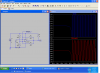
For a digitaly PWM modulator the maxium dutycycle may not be more than about 50% of the switching time. How can i simle made this with a LM393 comparator.
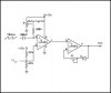
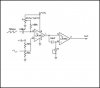
Here i have only one of the the comparators in use.
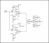
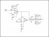
Or with the use with a Nand gate 4093.
The PWM signal is used in a PWM audio-modulator what modulate a AM transmitter.
 
Osillator

Something like this?
 

Attachments

  • osc.PNG
    osc.PNG
    74.7 KB · Views: 161
Thanks for reply, but how is it works is there a adjustment for limit the maxium duration of the duty-cycle?
I have some ideas in the attachments below.
Could anyone advise me of this is a good idea that may be work..
 

Attachments

  • jpg1.JPG
    jpg1.JPG
    20 KB · Views: 135
  • jpg2.JPG
    jpg2.JPG
    21 KB · Views: 139
  • jpg3.JPG
    jpg3.JPG
    32.6 KB · Views: 141
  • jpg4.JPG
    jpg4.JPG
    31.8 KB · Views: 147
Last edited:
Generate a sawtooth at twice the frequency of the output squarewave. Use that to PWM the twice-frequency square wave from 0-100%. Then AND that with the output waveform which is half the frequency of the modulated waveform. You will end up with the positive half of the output wave modulated from 0 to 100% but the negative half stays at zero due to the AND gate. This gives an output PWM of 0% to 50% maximum.
 
Thanks for reply.
I know the system what you descripe and i shall try this.
In earlyer experiments i have tried this with two flip-flops CD4013, where the second flip-flop is set with the pulse suration from the comparator and reset the time of 1/2
from the first flip-flop what devide the suare by 2.
But the modulation was not good, and distorted so something was not good in this circuit.
 

Attachments

  • flipflop.JPG
    flipflop.JPG
    39.2 KB · Views: 189
Last edited:
Status
Not open for further replies.

Latest threads

New Articles From Microcontroller Tips

Back
Top