Continue to Site

Welcome to our site!

Electro Tech is an online community (with over 170,000 members) who enjoy talking about and building electronic circuits, projects and gadgets. To participate you need to register. Registration is free. Click here to register now.

  • Welcome to our site! Electro Tech is an online community (with over 170,000 members) who enjoy talking about and building electronic circuits, projects and gadgets. To participate you need to register. Registration is free. Click here to register now.

Light Sound Trigger

Status
Not open for further replies.

gvi70000

Member
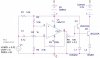
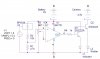
I think i got the final circuit if i did the simulation correct
i didn't manage to make the sound trigger to work with 3v battery so I'll use two instead. The sensitivity level is set by the potentiometer...
so i need experts opinion on this, do you think will work?
 

Attachments

  • Mic.JPG
    Mic.JPG
    62.2 KB · Views: 645
  • Light.JPG
    Light.JPG
    65.1 KB · Views: 737
Which circuit do you intend to use? The first one will have an output of Vcc/2 when there is no signal from the mic. I don't think that's the best way to do it. For the second, I don't know how U2 functions, so I can't comment.
 
I looked up U2. R2 and V1 have no apparent functions. Current amplification is best done with an inverting amp configuration.
 
Hello,
In the Light circuit v1 represents the light intensity . It is necessary to simulate the photo diode (at least this is what i found in orcad documentation). With R1 R2 i try to split the output of the photodiode in two to have a better comparation with the inverting input of the op amp. This one is intended to work as a light/dark sensor.

In the sound circuit i use V1 to simulate the microphone.

I need to use both circuits as triggers for a camera shutter.

Thanks for reply

PS: the first time i raise the problem here https://www.electro-tech-online.com/threads/light-darck-sound-sensor-problems.98125/
 
Last edited:
Hi
In the sound circuit i use Q1 as a preamp and lmv721 as comparator. To adjust the sensitivity i use R2 (475KOhn is the measured value).
In the light sensor R1 adjust the sensitivity.

So...do you think that these circuits will do the job?

PS: In the common-emitter configuration the led will be lit when the op amp output is 0, right? in this case i have to use PNP 2N2907 instead of 2N2222?
 

Attachments

  • Mic.JPG
    Mic.JPG
    68.8 KB · Views: 339
  • Light.JPG
    Light.JPG
    70.9 KB · Views: 266
Status
Not open for further replies.

Latest threads

New Articles From Microcontroller Tips

Back
Top