Continue to Site

Welcome to our site!

Electro Tech is an online community (with over 170,000 members) who enjoy talking about and building electronic circuits, projects and gadgets. To participate you need to register. Registration is free. Click here to register now.

  • Welcome to our site! Electro Tech is an online community (with over 170,000 members) who enjoy talking about and building electronic circuits, projects and gadgets. To participate you need to register. Registration is free. Click here to register now.

light dimmer

Status
Not open for further replies.

Fahime

New Member
Hi there,
Attached are 2 dimmer circuits. I have 2 questions about these circuits:
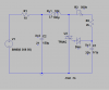
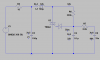
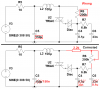
1) What is the difference between these two attached circuits? There are C6 and R7 in "dimmer-2.png" . What are they for?
2) I know that L1 and C2 make up a radio interface filter. Is it a resonant filter or a low pass filter? How does it work?
 

Attachments

  • dimmer-1.PNG
    dimmer-1.PNG
    20 KB · Views: 531
  • dimmer-2.PNG
    dimmer-2.PNG
    25.1 KB · Views: 411
I cropped and corrected the second circuit.
C6 and R7 form a second phase-shift circuit so that there is less hysteresis in the control (the first circuit needs to be turned up to about half brightness for the light to turn on).

The LC is a lowpass filter. The L blocks high frequencies and the C shunts the remainder to ground.
 

Attachments

  • light dimmer.PNG
    light dimmer.PNG
    30.7 KB · Views: 458
You say that R7 and C6 form a second phase shift. Please see the attached file(dim.png)
you know, triac is acting like a switch. So as soon as Vd1 and Vd2 equal 30V the Diac conducts and the triggers the triac. I drow the schematic and have changed the potentiometer value from zero to 500kohm. you can see the responses in attached files: dim-g0.png , dim-g50.png , dim-g500.png
As you can see in those files the responces of 2 circuits are very similar and There is a small phase shift that seems negligible. So I can't find out how R7 and C6 are improving the behavior of the circuit. Is there something the matter with it?
Regarding with the LC lowpass filter, Is it a filter in the times when triac is off? Because when the triac is on, it's a short circuite and L1 and C2 look in parallel. Am I right?
 

Attachments

  • dim-g0.PNG
    dim-g0.PNG
    36 KB · Views: 305
  • dim-g50.PNG
    dim-g50.PNG
    48.9 KB · Views: 276
  • dim-g500.PNG
    dim-g500.PNG
    43.9 KB · Views: 257
  • dim.PNG
    dim.PNG
    31.1 KB · Views: 279
Look in Google at Light Dimmer Circuits. https://www.epanorama.net/documents/lights/lightdimmer.html#120v
The good circuits have two RC phase-shifters. Maybe R6 and R7 in your circuit have the wrong values. Maybe your simulation program doesn't show the hysteresis when the light is completely off then the pot must be turned up to almost halfway to cause the light to begin glowing on a simple circuit but is much better with two phase-shifting circuits.

The lowpass filter keeps the high frequency switching harmonics out of the power line because the inductor is a high impedance to high frequencies then the capacitor is a low impedance to ground for remaining high frequencies.
 
audioguru said:
Look in Google at Light Dimmer Circuits. https://www.epanorama.net/documents/lights/lightdimmer.html#120v
Maybe R6 and R7 in your circuit have the wrong values. Maybe your simulation program doesn't show the hysteresis when the light is completely off then the pot must be turned up to almost halfway to cause the light to begin glowing on a simple circuit but is much better with two phase-shifting circuits.
R7 and R6 in my circuit is the same as the circuit you offer. So the problem is probably the simulation program. It's "SwitcherCAD III". I trust on you.
 
Status
Not open for further replies.

Latest threads

New Articles From Microcontroller Tips

Back
Top