Continue to Site

Welcome to our site!

Electro Tech is an online community (with over 170,000 members) who enjoy talking about and building electronic circuits, projects and gadgets. To participate you need to register. Registration is free. Click here to register now.

  • Welcome to our site! Electro Tech is an online community (with over 170,000 members) who enjoy talking about and building electronic circuits, projects and gadgets. To participate you need to register. Registration is free. Click here to register now.

Light activated circuit

Status
Not open for further replies.
S

Souper man

Guest
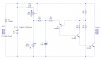
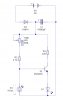
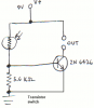
As for one of my new robot features (Farfalle, the walking robot), I wanted Farfalle to turn on when it is light out, using a photoresistor. The only problem is that I cant find a schematic that I am looking for. I was going to use a LM339 (quad Comp) or a LM324 (quad OPAMP). The output of the transistor would control the base of a PNP transistor, which would switch on the power supply to the 7805. For more details on Farfalle, go to the Farfalle:coming soon! thread under robotics chat. Also, it must be able to be ajustable using a potientiometer. Thanks!
 
Last edited by a moderator:
Search for 'dark activated switch', plenty on the web. I built on a while back for a solar garden light, LDR and 2 transistors. No idea where to look for the schematic right now, maybe after work.
 
Couldnt I just use a Comparator or an OPAMP, with a pot. and a LDR on the positive input side, and a 500k ohm resistor on the negative input side that then goes to ground, and the output controls a transistor that would control the negative bus. I think that would work, wouldnt it?
 
There likely a dozen different ways to do it. Here are a couple I found still on the computer, not the one I was looking for though.

Well, went a little crazy and dug up some more, most untested....
1 transistor
3 transistors
555
741

Quite a variety. I know you are interested in PIC, so didn't include my AVR work (still kind of buggy), but uses a red LED as the detector and the AVR's analog comparator.
 

Attachments

  • NightSwitch.jpg
    NightSwitch.jpg
    41.1 KB · Views: 170
  • DarkSwch.jpg
    DarkSwch.jpg
    45.1 KB · Views: 176
  • 555_dark.gif
    555_dark.gif
    3.1 KB · Views: 221
  • darksw.gif
    darksw.gif
    8.4 KB · Views: 173
  • light_annoy.gif
    light_annoy.gif
    4 KB · Views: 167
  • Transistor switch.PNG
    Transistor switch.PNG
    13.9 KB · Views: 258
Status
Not open for further replies.

New Articles From Microcontroller Tips

Back
Top