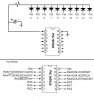
I am making a simple led binary clock. The first four LED are the hours in binary (read left to right). LEDS 6 through 10 are the minutes(read left to right) . I run an upload the code but minute LEDs seem to not work correctly. I am posting code and attaching schmatics. What am I doing wrong?
Thanks in advance
Thanks in advance
Code:
;
;  The "Dlay" macro in this routine will provide delays ranging
;   from 1 to 1,000,000 cycles.
;
;  Hardware Notes:
;   PIC16F684 running at 4 MHz in Simulator
;   Reset is tied directly to Vcc via Pullup/Programming Hardware
;
;
;  Myke Predko
;  04.09.22
;
  LIST R=DEC
 INCLUDE "p16f630.inc"

 __config (_INTRC_OSC_NOCLKOUT & _WDT_OFF & _PWRTE_OFF & _MCLRE_OFF & _CP_OFF )

 CBLOCK 0x020                ;  Variable Declaration
DlayValue:2                  ;  Requires 24 Bit Counter (w/ WREG)
minutes
hours
 ENDC

Dlay Macro Cycles
 variable CyclesLeft            ;  Keep Track of Remaining Cycles
 variable LargeNum
CyclesLeft = Cycles
 local LongLoop
 if Cycles > 0x04FFFF00         ;  Can't Handle the Anything > 83 Seconds (@ 4 MHz)
 error "Required Delay is longer than 'Dlay' Macro can support"
 endif
 if Cycles > 327681             ;  Need Large Loop?
LargeNum = CyclesLeft / 327681
  movlw   LargeNum
  movwf   DlayValue + 2         ;  Calculate Number of Loops
LongLoop:                       ;  Repeat for Each Loop
  clrf    DlayValue + 1         ;  Do Maximum Possible Loop Count
  clrf    DlayValue
  decf    DlayValue, f
  btfsc   STATUS, Z
   decfsz DlayValue + 1, f
    goto  $ - 3
  decfsz  DlayValue + 2, f      ;  Repeat Loop
   goto   LongLoop
CyclesLeft = CyclesLeft - ((LargeNum * 327681) + 1 + (LargeNum * 3))
 endif  ;  Need Large Loop
 if Cycles > 14                 ;  Will a Loop be required?
  movlw   high (((CyclesLeft - 3) / 5) + 256)
  movwf   DlayValue + 1
  movlw   low (((CyclesLeft - 3)/ 5) + 256)
  movwf   DlayValue
  decf    DlayValue, f          ;  5 Cycle Constant Delay Loop
  btfsc   STATUS, Z
   decfsz DlayValue + 1, f
    goto  $ - 3
CyclesLeft = CyclesLeft - (3 + (5 * ((CyclesLeft - 3)/ 5)))
 endif                          ;  Finished with Loop Code
 while CyclesLeft >= 2          ;  Put in 2 Instruction Cycle Delays
  goto    $ + 1
CyclesLeft = CyclesLeft - 2
 endw
 if CyclesLeft == 1             ;  Put in the Last Required Cycle
  nop
 endif
 endm

  PAGE

 org      0
  nop                        ;  Required for MPLAB ICD2

;////////////////////////////////////////////////////////////////;
;Luke BrownGold's Code

  bsf STATUS,5 ;Go to Bank 1
 	 TRIS PORTA ;Move 00000 onto TRISA ? all pins set to output
 	 TRIS PORTC ;Move 00000 onto TRISC ? all pins set to output
  bcf STATUS,5 ;Come back to Bank 0

	clrf PORTA
	clrf PORTC

	;set time
	movlw d'12' ;hours cant start at zero
	movwf hours
	clrf minutes ;start minutes at 0


  Start
			;Checks Hours and Minutes so the do not exceed time
			checkResetTime

			movf    minutes, w      ;  if minutes == numb60 then resetmin
			subwf   d'60', w
			btfsc   STATUS, Z
			goto   resetmin

			movf    hours, w      ;  if hours == numb13 then resethour
			subwf   d'13', w
			btfsc   STATUS, Z
			goto   resethour

			;clear display
 			clrf PORTA
			clrf PORTC


;/////////////////-------------HOURS
			BTFSS hours,d'3'
			BSF PORTA,d'4'

			BTFSS hours,d'2'
			BSF PORTC,d'5'

			BTFSS hours,d'1'
			BSF PORTC,d'4'

			BTFSS hours,d'0'
			BSF PORTC,d'3'


;/////////////////-------------Minutes
			BTFSS minutes,d'5'
			BSF PORTC,d'2'

			BTFSS minutes,d'4'
			BSF PORTC,d'1'

			BTFSS minutes,d'3'
			BSF PORTC,d'0'

			BTFSS minutes,d'2' ;
			BSF PORTA,d'2' ;

			BTFSS minutes,d'1'
			BSF PORTA,d'1'

			BTFSS minutes,0
			BSF PORTA,d'0'


			call oneSec ;will increase delay later (shorter for testing purposes)

			incf minutes, f  ;increments minutes


  goto Start

 resetmin   movlw d'0'
			movwf minutes
			incf hours, f  ;increments hours
			goto checkResetTime

 resethour  movlw d'1'
			movwf hours
			goto checkResetTime
oneSec:
			Dlay 100000                 ;  Delay 0.1s
			Dlay 100000                 ;  Delay 0.1s
			Dlay 100000                 ;  Delay 0.1s
			Dlay 100000                 ;  Delay 0.1s
			Dlay 100000                 ;  Delay 0.1s
			Dlay 100000                 ;  Delay 0.1s
			Dlay 100000                 ;  Delay 0.1s
			Dlay 100000                 ;  Delay 0.1s
			Dlay 100000                 ;  Delay 0.1s
			Dlay 100000                 ;  Delay 0.1s
  			nop
			nop
return

tenSec:
		Call oneSec
		Call oneSec
		Call oneSec
		Call oneSec
		Call oneSec
		Call oneSec
		Call oneSec
		Call oneSec
		Call oneSec
		Call oneSec
return
  end