EditorInChief
New Member
I have **broken link removed** - a fairly low quality LED light for video. The build quality I would rate as 'indifferent' - but that's another story.
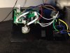
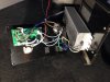
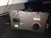
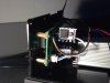
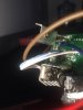
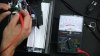
After taking it to a location and back to the office, it quit working, so I tested the leads from the power supply unit that go to the light head. In so doing, I shorted between two of the leads with my probe (yes, I am a dolt.)
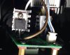
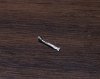
Magically, the unit started working again, but now it doesn't dim. Strangely, the 0-100% LED readout on the front of the light still changes from 0-100% as I spin the knob, the light just doesn't dim. So I'm guessing that the pot is fine, but maybe one of the two larger transistors is fried (by yours truly.) I've attached photos of the whole situation and especially the two transistors, which I assume I should just try to buy online and then replace, but I want to make sure to get the right transistor.
One of them seems to be "irf1018e IUR p216d 72RA" and the other seems to start with a snaky squiggle and then have "JM02RP M25701" and then "-12 P+" which I assume refers to polarity.
Can anyone help me find where to order new transistors?
After taking it to a location and back to the office, it quit working, so I tested the leads from the power supply unit that go to the light head. In so doing, I shorted between two of the leads with my probe (yes, I am a dolt.)
Magically, the unit started working again, but now it doesn't dim. Strangely, the 0-100% LED readout on the front of the light still changes from 0-100% as I spin the knob, the light just doesn't dim. So I'm guessing that the pot is fine, but maybe one of the two larger transistors is fried (by yours truly.) I've attached photos of the whole situation and especially the two transistors, which I assume I should just try to buy online and then replace, but I want to make sure to get the right transistor.
One of them seems to be "irf1018e IUR p216d 72RA" and the other seems to start with a snaky squiggle and then have "JM02RP M25701" and then "-12 P+" which I assume refers to polarity.
Can anyone help me find where to order new transistors?